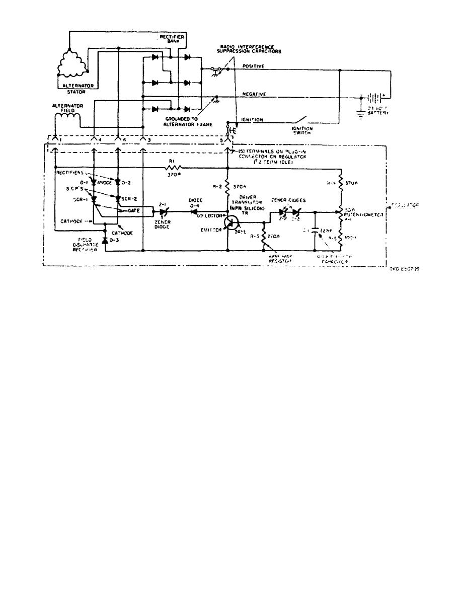
Figure 43.
Schematic of regulator.
(1) Assume the regulator is set to regulate the direct current output
voltage at approximately 28 volts.
(2) After the vehicle engine has been started, the battery voltage is
normally lower than the required alternator output voltage for which the regulator
has been set (approximately 28 volts). The voltage at the movable contact of
potentiometer P1 is therefore lower than the combined voltages of zener diodes Z2
and Z3. No current can flow in the base circuit of transistor TR, and the
transistor displays a high resistance from emitter to collector. The voltage
across the transistor, emitter to collector, is greater than the voltage of zener
diode Z1 and control current therefore flows in the gate to cathode circuit of
silicon controlled rectifiers SCR1 and SCR2 turning them ON.
(3) This control current, plus the current passed through R1, plus the
residual magnetism in the alternator rotor, builds up the output voltage of the
alternator. As the voltage builds up, silicon controlled rectifiers SCR1 and SCR2
alternately carry field current, as the phase terminal to which each silicon
controlled rectifier is connected becomes positive. This additional field current
builds up to line voltage almost instantaneously, even at engine idle speed. Each
silicon controlled rectifier stops conducting field current from anode to cathode
whenever its phase terminal reaches zero voltage. The alternate firing of
rectifiers SCR1 and SCR2 supplies sufficient field current to provide rated
performance from the alternator.
(4) When this field current builds up the output voltage beyond the
required level, the voltage at the movable contact on potentiometer P1 exceeds the
combined voltages of zener diodes Z2 and Z3. Current therefore flows in the base-
to-emitter circuit of transistor TR. This base current
OS 010, 1-P23


 Previous Page
