(3) On the front of the drive end housing is a cover plate (26) which
allows access to the 40/60-ampere regulator taps.
(4) On the circumference of the drive end housing is a pipe plug (24).
Beneath this plug is the voltage output adjustment for the generator.
b. With the drive end housing removed, six rectifying diodes are exposed
within the intermediate housing along with the brushes and sliprings on the rotor
(fig 9).
c. From this point the stator assembly containing the DELTA connected coils
can be removed.
d.
The end housing then can be removed from the rotor with the puller.
SECTION II.
GENERATOR TESTS
2. GENERATOR TESTS. In addition to checking the bearings in the generator
housings, the following checks are performed.
a. Output voltage and current into specific loads to check the regulator
and generator capabilities.
b.
Rotor checks for shorts and opens.
c.
Stator checks for opens and shorts.
d.
Diode checks of forward to back resistance.
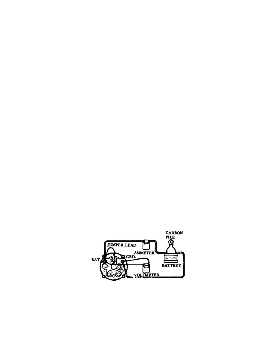
3. GENERATOR OUTPUT. To check the generator output, you must first know the
voltage and current output specifications. The equipment required is an ammeter,
voltmeter, battery, and a variable resistance load such as a carbon pile.
a. The generator has a BAT terminal and ignition terminal. The BAT
terminal is the battery charging circuit. The ignition terminal is normally
energized when the ignition switch is turned ON. Through the ignition terminal,
the regulator circuit and exciter field winding receive their operating current and
voltage.
b. When testing a generator on the bench, the ignition terminal and battery
terminal are connected by a Jumper.
c.
The ammeter is connected in series during the generator output check
(fig 1).
Figure 1.
Output check.
OS 010, 2-P2


 Previous Page
