

M2/M3 BFV: FIRE CONTROL SYSTEM - OD1608 - LESSON 1/TASK 1
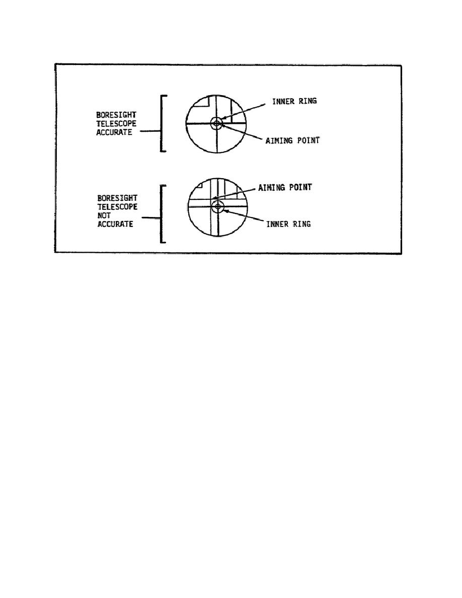
FIGURE 12.
TESTING THE BORESIGHT RETICLE.
(23) Check the alignment of the gun reticle on the aiming point
of the target. If the gun reticle is not aligned on the aiming point
of the target, it must be aligned as described in step (24) below.
If the gun reticle is aligned on the aiming point of the target, the
boresight telescope and adapter may be removed from the barrel as
described in paragraph 3b(25) on the following page.
(24) To align the gun reticle on the aiming point of the target,
follow these steps:
(a) Lift the GUN BORESIGHT cover (figure 13 on the following
page).
(b) Turn the EL (elevation) knob to align the elevation of
the gun reticle on the aiming point of the target.
(c) Turn the AZ (azimuth) knob to align the azimuth of the
gun reticle on the aiming point of the target.
(d) If the gun reticle does not align on the aiming point of
the target, troubleshooting must be performed (TM 9-2350-252-20-2-1,
chapter 3).
(e) Assuming that the gun reticle can be aligned with the
aiming point of the target, close the GUN BORESIGHT cover.
15


 Previous Page
