

M2/M3 BFV: FIRE CONTROL SYSTEM - OD1608 - LESSON 1/TASK 1
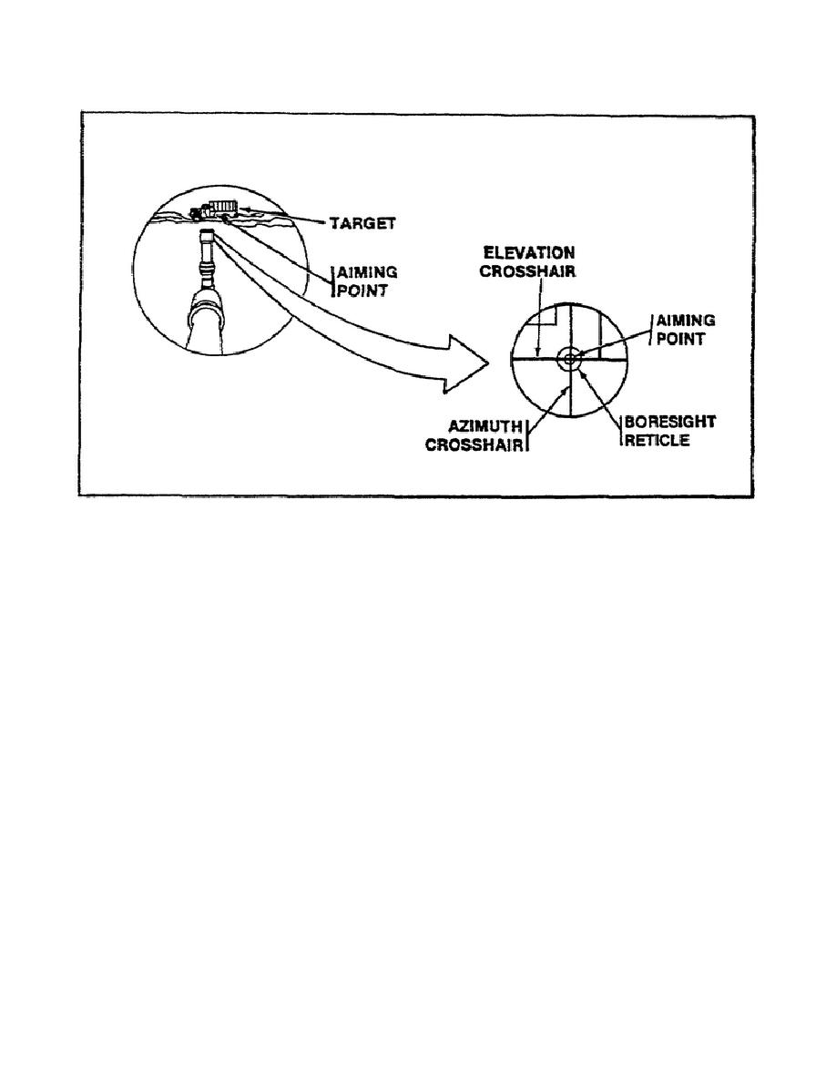
FIGURE 11.
ALIGNING THE ELEVATION AND
AZIMUTH CROSSHAIRS.
(20) The next step is aligning the azimuth crosshair in the
boresight reticle on the aiming point of the target (figure 11). To
accomplish this, the turret is manually traversed, as needed.
(21) Now that the boresight reticle is aligned, the accuracy of
the boresight telescope must be checked.
To do this, rotate the
boresight telescope 90 to the right, and look at the aiming point in
the boresight reticle. Then rotate the boresight telescope 90 to the
left and look at the aiming point in the boresight reticle.
The
aiming point should stay in the inner ring (figure 12 on the
following page) of the boresight reticle. If the aiming point moved
out of the inner ring of the boresight reticle, the boresight
telescope is not accurate.
When this happens, insert another
boresight telescope and repeat steps (17) through (21) of this
procedure.
If the aiming point stayed in the inner ring of the
boresight reticle for both rotations, continue with boresighting.
(22) Once it has been established that the boresight telescope
is accurate, the focus barrel must be turned to focus the gun
reticle.
The boresight reticle and the gun reticle must be focused
on the same aiming point of the target.
14


 Previous Page
