

M2/M3 BFV:
STEERING SYSTEM - OD1605 - LESSON 1/TASK 1
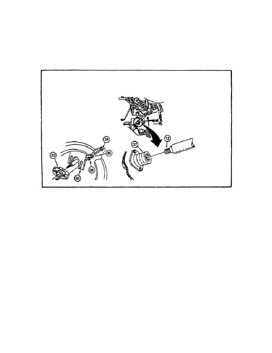
Step 8.
Remove support bearing (32) from bracket (33) by removing
two screws (34), lockwashers (35), and washers (36)(see figure 19).
Step 9.
Remove shaft (12) from bellows (37)(see figure 19).
FIGURE 19.
REMOVING SUPPORT BEARING
AND SHAFT.
(3) Procedural Steps for Installing the Steering Shaft Assembly.
Step 1.
Install shaft (12) through bellows (37) (see figure 19).
WARNING
Loss of steering control can cause vehicle to
crash.
Crash could kill or injure soldiers.
Install NEW locknuts and lockwashers.
Step 2.
Install support bearing (32) on bracket (33) by installing
two washers (36), new lockwashers (35), and screws (34) on bracket
(33). Be sure to install screws finger tight (see figure 19).
27


 Previous Page
