

M2/M3 BFV:
STEERING SYSTEM - OD1605 - LESSON 1/TASK 1
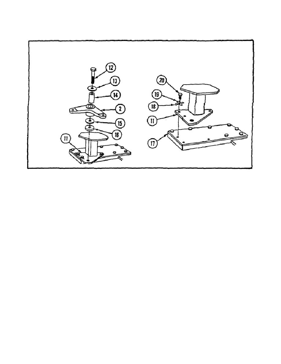
FIGURE 13.
REMOVING BELLCRANK AND PLATE.
Step 2.
Install spacer (16), washer (15), bellcrank (2), spacer
(14), washer (13), and screw (12) on plate (11) and torque screw (12)
to 164 - 288 in-lb (189 - 331 cm-kg) using a torque wrench and socket
(see figure 13).
Step 3.
Install link (7), three washers (10), screw (9), and new
locknut (8) on bellcrank (2) (refer to figure 12 on the previous
page).
Step 4.
Install link (1), three washers (5), screw (4), and new
locknut (3) on lever (2)(refer to figure 11 on page 20).
Step 5.
Adjust and install the opposite connecting link at the
bellcrank by performing steps 6 through 8.
Step 6.
Center the yoke and adjust bearing (21) by turning the
bearing in or out to align with bellcrank (2) for free pin fit (see
figure 14 on the following page).
Step 7. Install link (1) on bellcrank (2) by installing screw (5),
three washers (6), link (1), and new locknut (8)(see figure 14).
Step 8.
Tighten jam nut (22) against link (1)(see figure 14).
22


 Previous Page
