MILLING MACHINE OPERATIONS - OD1644 - LESSON 1/TASK 1
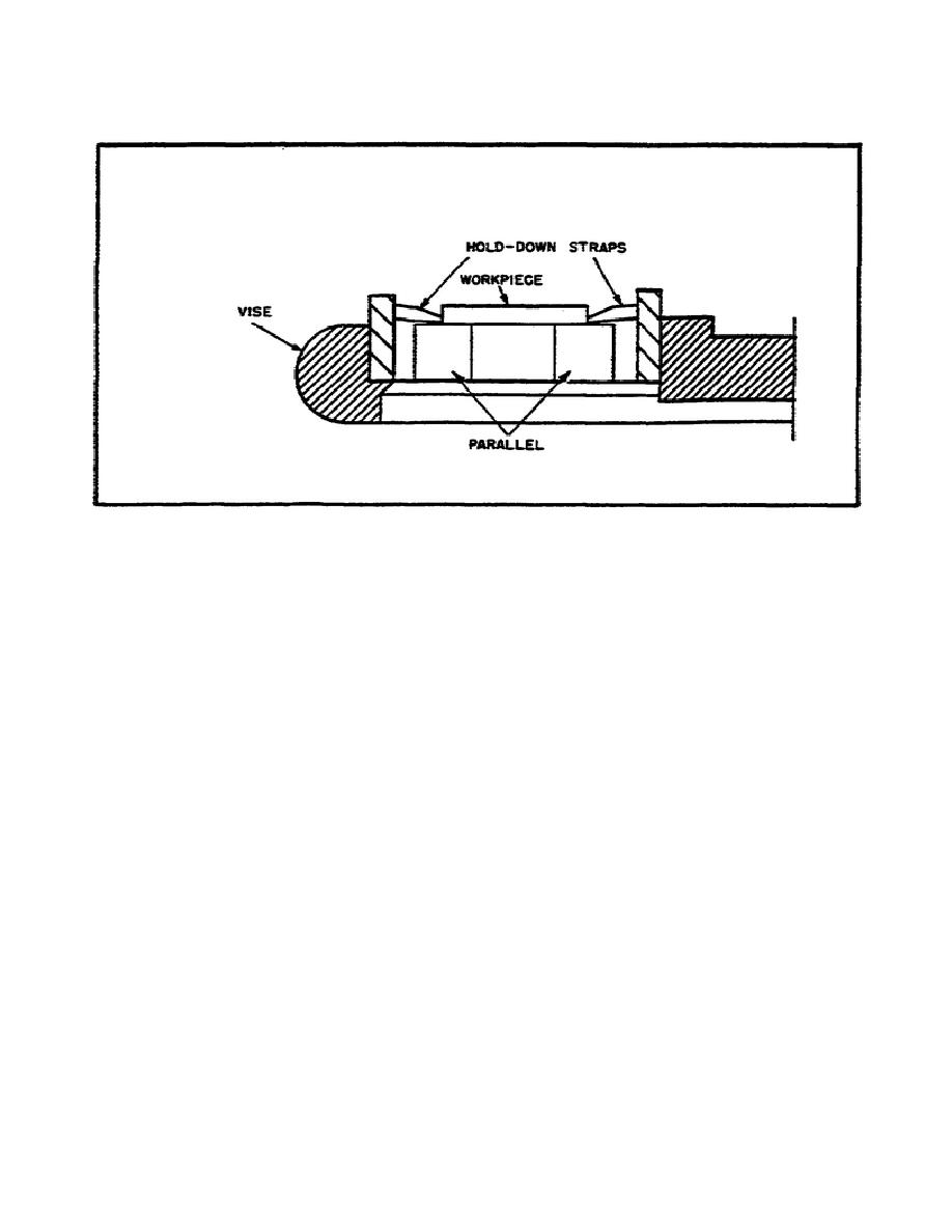
FIGURE 9.
APPLICATION OF HOLDDOWN STRAPS.
(2)
Index Head.
The bead of the indexing fixture contains an indexing
mechanism, used to control the rotation of the index head spindle in order
to space or divide a workpiece accurately. A simple indexing mechanism is
illustrated in figure 10 on the following page. It consists of a 40-tooth
worm wheel fastened to the index head spindle, a single-cut worm, a crank
for turning the wormshaft, and an index plate and sector. Since there are
40 teeth in the worm wheel, one turn of the index crank causes the worm
wheel, and consequently the index head spindle to, make one-fortieth of a
turn; so 40 turns of the index crank revolves the spindle one full turn.
(3)
Plain Indexing.
The following principles apply to basic indexing of
workpieces:
(a)
Suppose it is desired to mill a spur gear with 8 equally spaced
teeth.
Since 40 turns of the index crank will turn the spindle one full
turn, one-eighth of 40, or 5 turns of the crank after each cut, will space
the gear for 8 teeth.
(b)
The same principle applies whether or not the divisions required
divide evenly into 40.
For example, if it is desired to index for 6
divisions, 6 divided into 40 equals 6 2/3 turns; similarly, to index for 14
spaces, 14 divided into 40 equals 2 6/7 turns.
Therefore, the following
rule can be derived: to determine the number of turns of the index crank
needed to obtain one division of any number of equal divisions on the
workpiece, divide
22


 Previous Page
