

MILLING MACHINE OPERATIONS - OD1644 - LESSON 1/TASK 1
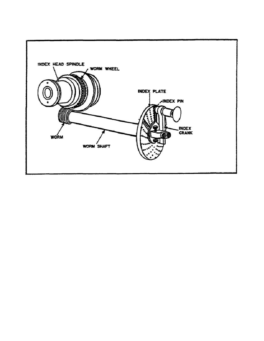
FIGURE 10.
SIMPLE INDEXING MECHANISM.
40 by the number of equal divisions desired (provided the worm wheel has 40
teeth, which is standard practice).
(4)
Index Plate. The index plate (figure 11 on the following page) is a
round metal plate with a series of six or more circles of equally spaced
holes; the index pin on the crank can be inserted in any hole in any circle.
With the interchangeable plates regularly furnished with most index heads,
the spacings necessary for most gears, boltheads, milling cutters, splines,
and so forth, can be obtained. The following sets of plates are standard
equipment:
(a)
Brown and Sharpe type, 3 plates of 6 circles, each drilled as
follows:
Plate 1- 15, 16, 17, 18, 19, 20 holes.
Plate 2- 21, 23, 27, 29, 31, 33 holes.
Plate 3- 37, 39, 41, 43, 47, 49 holes.
(b)
Cincinnati type,
one
plate
drilled
on
both
sides
with
circles
divided as follows:
23


 Previous Page
