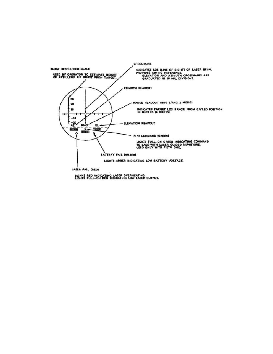
digit displays for azimuth (AZ), range (RNG), and elevation (EL).
Three
colored light indicators are also visible in the eyepiece display; the LASER
FAIL light (red) at the bottom left, the FIRE COMMAND light (green) in the
lower middle of the display, and the BATTERY FAIL light (amber) at the lower
right of the display.
Figure 1-8.
G/VLLD Eyepiece Display.
Also located on the exterior of the LD/R are four electrical connectors that
interface the LD/R and the other associated equipment, and provide you with
a testing and troubleshooting capability. The TU connector (1J2) interfaces
the TU and the LD/R to provide power to the TU and to allow azimuth and
elevation data to be transmitted to the LD/R.
Maintenance fixtures allow
for servicing of the unit.
b. Traversing Unit.
The TU also includes controls and indicators to
aid the operator. Most of the controls on the TU, however, are mechanical.
The TU provides two mounting flanges to mate the LD/R and the tripod to it.
The TU also provides a mounting surface for the night sight when used.
On top of the TU is a bubble level indicator to aid you when leveling the
G/VLLD set. The TU has a right-hand grip that allows you to rotate the TU
(and the LD/R) in azimuth and elevation. Gimbal locks secure the unit when
you attain the proper azimuth/elevation.
The interface connector (3P1)
electrically connects the TU and the LD/R.
11
OD1722


 Previous Page
