

the DOWN push button between terminals C and D (Fig. 65).
If
continuity is not indicated at both test points, the switch is
defective, repair or replace the switch.
Assume the switch
functions properly, connect the cable, and continue to
troubleshoot the system.
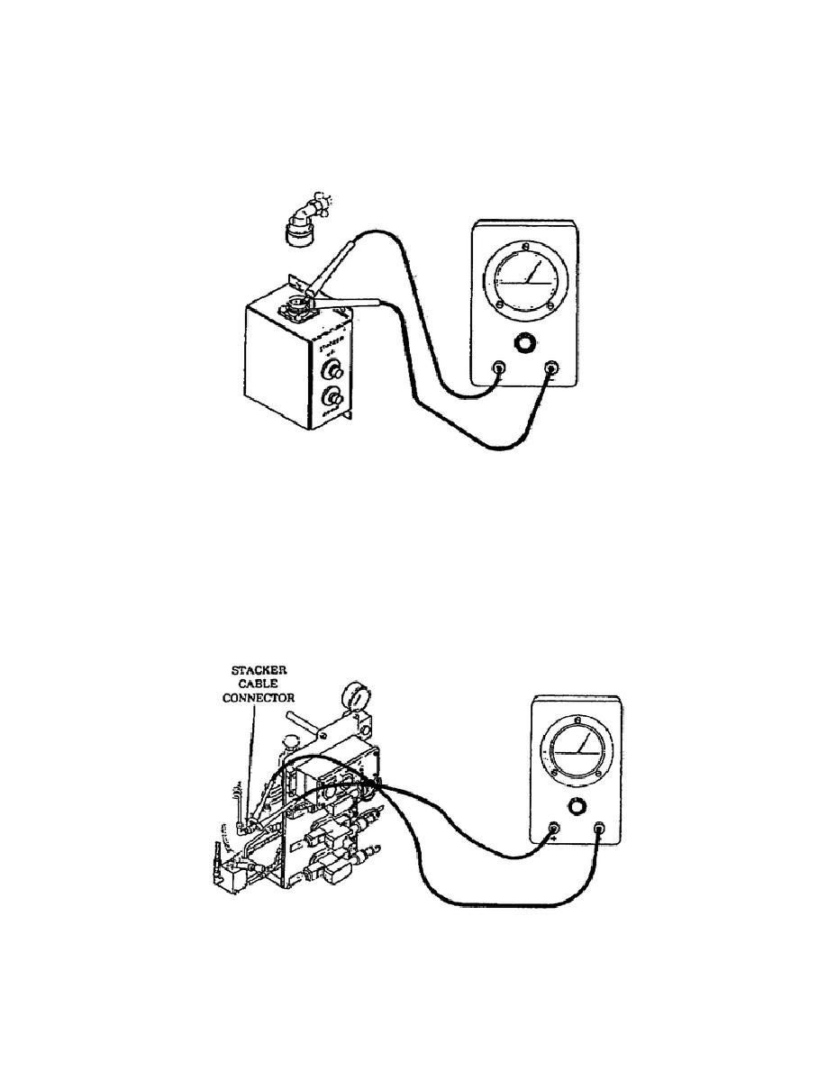
Figure 65.
Stacker Control Switch Test Point.
o Disconnect the stacker control switch cable at the stacker cable
connector. Push the UP push button of the stacker control switch
box, test the cable lead continuity between pins A and B, press
the DOWN push button, and test the continuity of the cable lead
between pins C and D (Fig. 66). If no continuity is indicated at
both test points, repair or replace the cable.
Assume that
continuity was indicated at both test points, connect the cable,
and continue troubleshooting the system.
Figure 66.
Stacker Cable Test Point.
64
OD1703

 Previous Page
