BASIC ELECTRONICS - OD1633 - LESSON 1/TASK 2
While these circuits may appear to be different, the two drawings actually
represent the same circuit.
The drawing in figure 55, view B, on the
previous page is the familiar box-like structure and may be easier to work
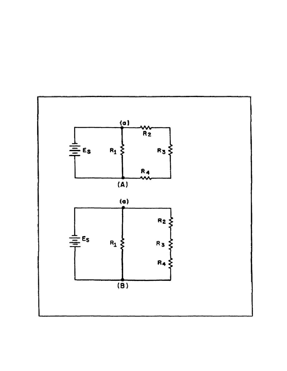
with. Figure 56, view A, is a schematic of a circuit shown in a box-like
structure, but way be misleading.
This circuit in reality is a series-
parallel circuit that may be redrawn as shown in figure 56, view B.
The
drawing in view B of the figure is a simpler representation of the original
circuit and could be reduced to just two resistors in parallel.
FIGURE 56.
REDRAWING A SIMPLE SERIES-PARALLEL CIRCUIT.
91


 Previous Page
