BASIC ELECTRONICS - OD1633 - LESSON 1/TASK 2
20 volts + (I x 60 Ohms) + (-180 volts) + 40 volts + (I x 20 Ohms) = 0
20 volts - 180 volts + 40 volts 4 (C x 60 Ohms) + (I x 20 Ohms) = 0
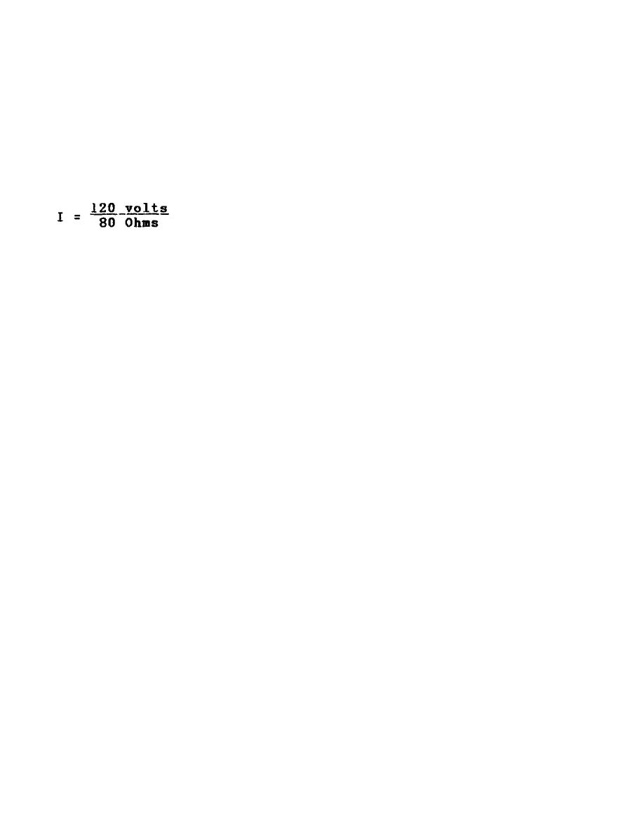
-120 volts + (I x 80 Ohms) = 0
I x 80 Ohms = 120 volts
I = 1.5 amps
4.
Circuit Terms and Characteristics
Before you learn about the type of circuits other than the series circuit,
you should become familiar with some of the terms and characteristics used
in electrical circuits.
These terms and characteristics will be used
throughout your study of electricity and electronics.
a. Reference Point. A reference point is an arbitrarily chosen point
to which all other points in the circuit are compared. In series circuits,
any point can be chosen as a reference and the electrical potential at all
other points can be determined in reference to that point. In figure 33, on
the following page, point A should be considered the reference point. Each
series resistor in the illustrated circuit is of equal value. The applied
voltage is equally distributed across each resistor. The potential at point
B is 25 volts more positive than at point A. Points C and D are 50 volts
and 75 volts, more positive than point A respectively.
When point B is used as the reference, as in figure 34 on the following
page, point D would be positive 50 volts in respect to the new reference
point.
The former reference point A, is 25 volts negative in respect to
point B.
As in the previous circuit illustration, the reference point of a circuit is
always considered to be at zero potential. Since the earth (ground) is said
to be at a zero potential, the term ground is used to denote a common
electrical point of zero potential. In figure 35, on page 60, point A is
the zero reference, or ground, and the symbol for
58


 Previous Page
