M2/M3 BFV ENGINE STARTING/CHARGING SYS - OD1603 - LESSON 1/TASK 1
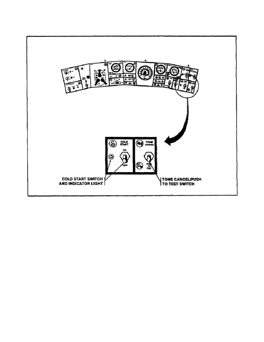
FIGURE 8.
COLD START SWITCH LOCATION.
Step 6.
Test Number 90 in step 5 above revealed a generator current draw
greater than 180 amperes.
With the STE-M1 still connected, Test Number 82
(GENERATOR VOLTAGE) should be performed next.
Because the vehicle is being
operated in a temperate (normal) climate, the voltage reading should be 28.6 .3
volts.
Step 7.
Test Number 82 revealed a voltage reading of 28.6 .3 volts. Move the
ENGINE ACCESSORY switch (3)(figure 1 on page 8) to the OFF position.
As the
accessory switch was turned off, the STE-M1 shows a voltage drop reading below 28.6
.3 volts.
This voltage drop indicates that the generator voltage regulator
(3)(figure 9 on the following page) is defective and must be replaced.
Step 8.
Disconnect the STE-M1 jack 1A1J14 (7) (figure 1, page 8) of the vehicle
distribution box (5), and replace the generator voltage regulator.
The generator
voltage regulator should be replaced as described in the following subparagraph.
24


 Previous Page
