LASER PULSE MONITOR mode - The LR Tester allows the
transmitted LR optical pulse to be monitored as an aid in
troubleshooting the LR.
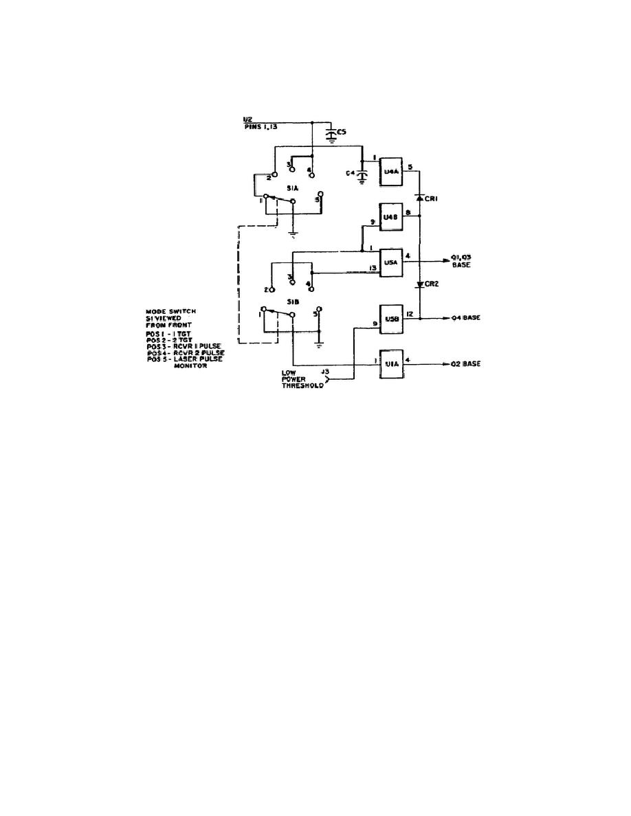
Figure 1-10.
MODE Switch Simplified Schematic.
The MODE switch has three wafers. Only wafers A and B are used (see
figure 1-10).
The switch contacts make or break connections to
components on the electronics board.
Two laser output indicators are located on the front panel of the LR
Tester. The NORMAL OUTPUT indicator DS2 (figure 1-9, item 22) lights
green when the optical energy is above 9.0 millijoules.
The LOW
OUTPUT indicator DS3 (figure 1-9, item 21) lights red whenever the
received optical energy exceeds 6.0 millijoules and the NORMAL OUTPUT
indicator is off. If neither light comes on, received optical energy
is less than 5.0 millijoules. The lights are reset by pressing the
RESET switch S2 (figure 1-9, item 19). DS2 and DS3 are press-to-test
indicators.
The LR Tester front panel also houses three pulse monitoring jacks.
Two synchronized pulses are used to help troubleshoot the LR.
The
TGT SYNC pulse is generated prior to each transmitted optical pulse
or pulse pair in all operating modes.
The RCVR SYNC pulse is
generated for each received LR optical pulse.
Both sync pulses are
available for monitoring at front panel jacks:
TGT SYNC at J4
(figure 1-9, item 14), and RCVR
16
OD1716


 Previous Page
