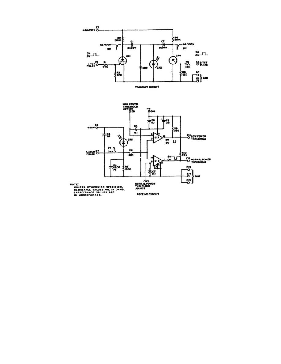
Figure 1-12.
XMT/RCV Board Assembly Schematic.
5.
Operational Process.
When the LR Test Set is being used to test the LR, optical energy
from the LR is diffused and attenuated in the receiving optics. The
diffusion minimizes the LR alignment sensitivity.
The aperture
reduces the LR output to a safe level for the PIN diode (see figure
1-13). The PIN diode detector converts optical power received to an
electrical charge.
The electrical charge is compared to reference
voltages in two comparators, lighting the LASER OUTPUT NORMAL or the
LASER OUTPUT LOW indicators, as applicable.
The range timer U4B, upon timing out, triggers the multiple targets
timer U5A. If the MODE switch is set to 2 TGT or RCVR 2 PULSE, the
range timer triggers the 2-target pulse generator U1A. The output of
the multiple target timer U5A drives the 1-target driver Q1. This in
turn connects to the LED
20
OD1716


 Previous Page
