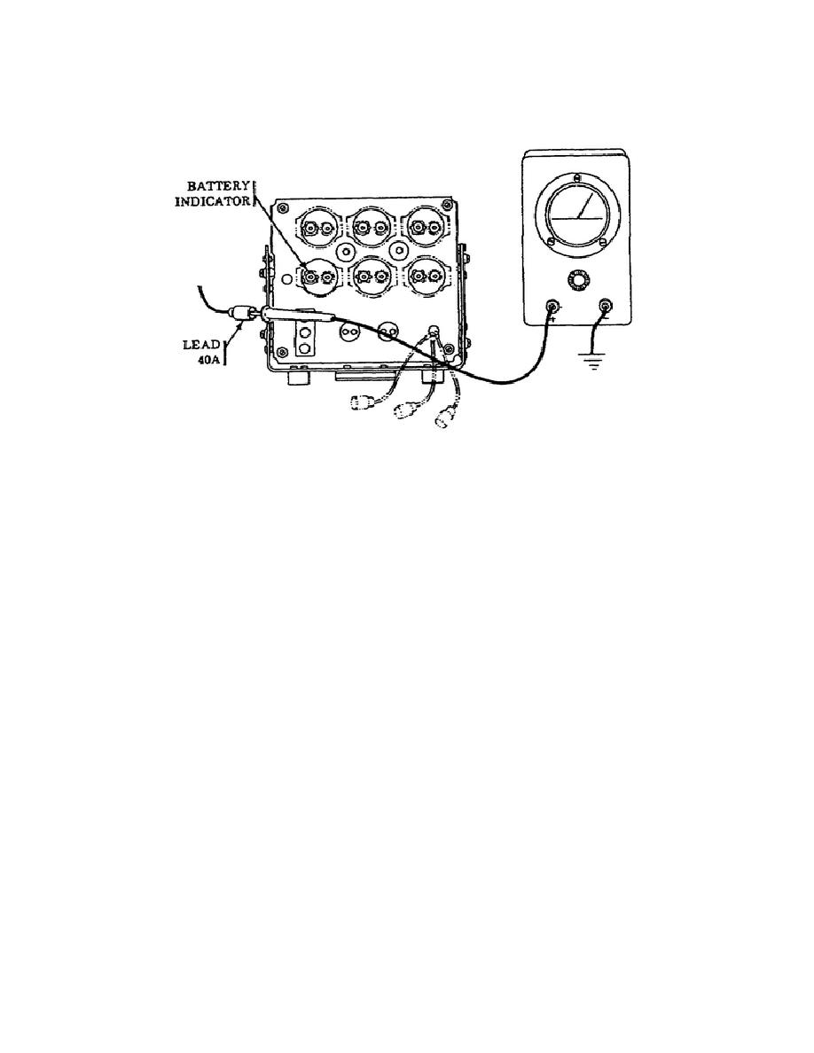
nominal 24 vdc. If the correct voltage is indicated, the indicator requires
replacement.
If voltage was incorrect, the portable panel circuitry
requires troubleshooting (Figure 27).
Figure 27.
Battery Indicator Lead 40A.
o
If an incorrect voltage reading was indicated during the battery
test, then the APU generator output must be tested.
NOTE:
To gain access to the APU generator, remove air intake plenum as
shown in TM 9-2350-267-20.
o
With the APU in the operational mode and the APU GENerator switch
ON, place the red multimeter probe on terminal B of the APU
generator and ground the black probe. The meter reading should
indicate 28 0.7 vdc (Figure 28).
If the correct voltage is
indicated, then lead 62 of the generator plug of the APU voltage
regulator requires testing.
If incorrect voltage is indicated,
then a resistance measurement must be taken on pin F at the
generator plug at the voltage regulator.
o
To test lead 62 of the generator plug of the APU voltage
regulator, use the red probe of the multimeter and probe through
the insulation of lead 62 and ground the black probe. The meter
should read 28 0.7 vdc. If the improper voltage is indicated,
repair or replace lead 62 from APU voltage regulator to APU
generator (Figure 29).
28
OD1702


 Previous Page
