o
When measuring the resistance from pin F of the generator plug to
ground, the reading was 2 ohms, which is acceptable. Therefore,
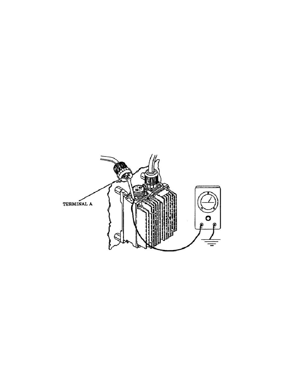
a voltage measurement of voltage regulator generator harness plug
terminal A is necessary. Make sure the GENerator switch is OFF
and set the MASTER switch to the ON position and start the APU.
Measure the voltage by placing the multimeter red probe on the
voltage regulator generator harness plug terminal A and ground
the black probe.
A meter reading of 2 1.5 vdc should be
obtained. If a correct voltage reading is indicated, replace the
voltage regulator IAW TM 9-2350-267-20 (Figure 34).
o
If incorrect voltage is indicated when testing the voltage
regulator generator harness plug terminal A, then a voltage check
of APU generator terminal B must be made. You perform this check
by placing the red multimeter probe on APU generator terminal B
and ground the black probe. The meter should indicate a 2 1.5
vdc. If voltage is correct, troubleshoot circuit 62 wiring from
the APU generator to APU voltage regulator and repair or replace
defective wiring or components IAW TM 9-2350-267-20.
If
incorrect voltage is indicated, replace the APU generator IAW TM
9-2350-267-20 (Figure 35).
Figure 34.
APU Voltage Regulator Generator Harness
Plug Terminal A.
32
OD1702


 Previous Page
