

o
If you suspect fuel contamination, drain the fuel
tanks
and
refill with new fuel as outlined in TM 9-2350-267-10.
8.
Troubleshooting the APU Generator Charging System
When Battery
Indicator Reads in Yellow or Red Regions With APU
Operating and
Generator Switch in ON Position.
NOTE:
Portable instrument panel battery indications (approximate):
23.5
1Vdc-d-yellow
26
Vdc-mid-scale (gage)
28
Vdc-mid-green
Apply the following steps when troubleshooting the APU generator charging
system:
o
The first troubleshooting step in this portion of the subcourse
is to operate the APU set and place the APU GENerator switch to
the ON position IAW the procedures shown in TM 9-2350-267-10.
o
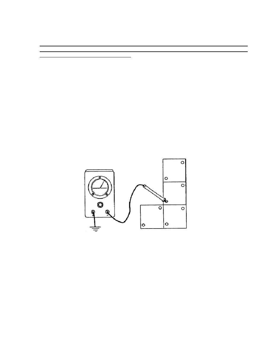
Test battery voltage by placing the multimeter red probe on the
battery positive terminal 62/81 and ground the black probe. The
meter should indicate a nominal reading of 24 vdc (Figure 26).
Figure 26.
Battery Voltage Test Procedure.
If the correct voltage was indicated, turn the MASTER switch OFF and remove
the portable instrument panel from its cover but do not disconnect the
harness or leads.
Disconnect lead 40A from the battery indicator and
connect the multimeter red probe to lead 40A ground the black probe. Set
the MASTER switch to the ON position and read the meter.
Meter reading
should indicate a
27
OD1702


 Previous Page
