

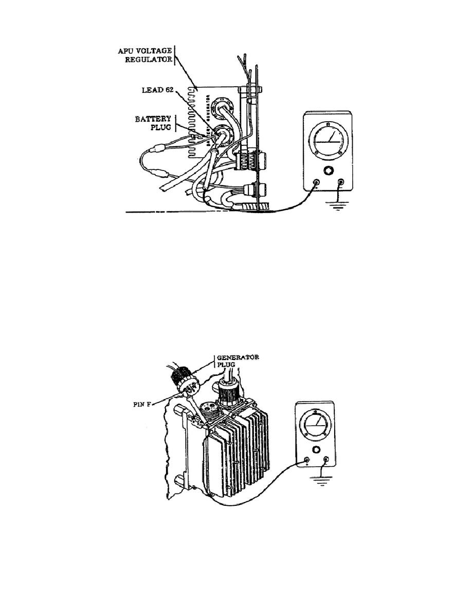
Figure 30.
APU Battery Plug Lead 62.
o
When testing APU generator output at terminal B, during generator
operation, a meter reading of 28 0.7 vdc was not indicated. As
a result, a resistance measurement is required to be taken at pin
F of the generator plug. Before you take this measurement, the
APU must be shut off and the MASTER switch set to the OFF
position. At this point, disconnect the generator plug from the
APU voltage regulator and set the APU GENerator switch to the ON
position.
Measure the resistance from pin F of the plug to
ground.
A resistance reading of 2 ohms should be indicated
(Figure 31).
Figure 31.
APU Generator Plug - Terminal F.
30
OD1702


 Previous Page
