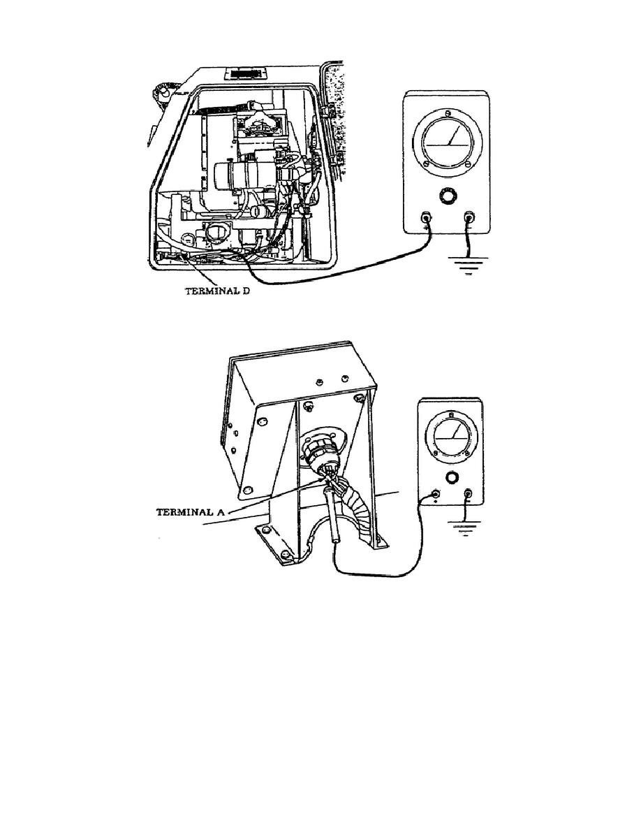
• Home
  • Download PDF
  • Order CD-ROM
  • Order in Print

Home > Ordnance Documents and other related manuals > > Figure 22. APU Harness Plug, Terminal D, Lead 487.
Troubleshooting the APU When Engine Starts But Fails to Keep Running
Figure 24. APU Control Box Continuity Test Chart.

Troubleshooting the Auxiliary Power Unit (APU) M992 carrier, Ammunition,
Page Navigation
  17    18    19    20    21  22  23    24    25    26    27  

Figure 22.
APU Harness Plug, Terminal D, Lead 487.
Figure 23.
APU Control Box Lead 487, Terminal A.
If voltage was indicated during this test, proceed to the next required test
as follows:
o
Set the  MASTER switch to the  OFF position.
Conduct an APU
control box continuity as shown on the chart (Figure 24).  If the
multimeter does not indicate the prescribed readings shown in
column 3 and 4 of the test chart, then a check of each circuit
wire, switch, and circuit breaker
22
OD1702


Western Governors University

< Previous Page
Index ^
Next Page >

Privacy Statement
Press Release
Contact

© Copyright Integrated Publishing, Inc.. All Rights Reserved. Design by Strategico.