

using the schematic and illustrations in TM 9-2350-267-20 will be
required.
Defective wiring or components will be repaired or
replaced as necessary.
If the APU control box is working properly and the APU still will not crank,
the following test will be performed:
o
Reconnect the APU control box connector and set the MASTER switch
to the ON position.
Conduct a voltage check by placing the
multimeter red probe on preheat solenoid terminal 65 and R and
ground the black probe (Figure 25). If no voltage is indicated,
the preheat solenoid is defective and Support Maintenance must be
notified.
5.
Troubleshooting the APU When Engine is Hard to Start/Hard to Start in
NOTE:
During extreme cold weather conditions, 0 to -65 degrees, install
the winterization kit.
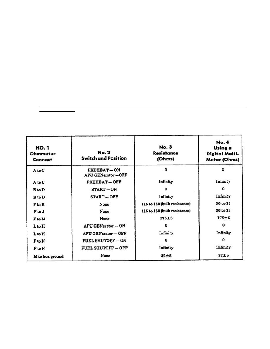
Figure 24.
APU Control Box Continuity Test Chart.
23
OD1702


 Previous Page
