TROUBLESHOOTING THE M998 ELECT SYST. - OD1617 - LESSON 1/TASK 1
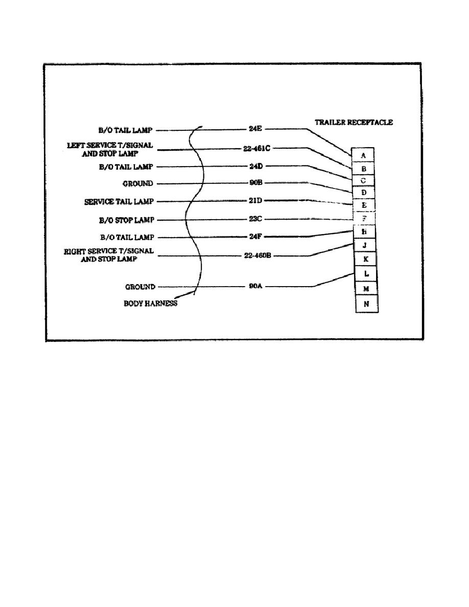
FIGURE 8.
TRAILER CONNECTION SYSTEM SCHEMATIC.
Step 3. Position the light switch in the circuit being tested (refer
to table 2, on the following page).
Using the multimeter, connect
the ground lead to terminal L on the trailer receptacle. Using the
trailer receptacle circuit chart, connect the positive lead from the
multimeter to the circuit terminal in the trailer receptacle being
tested.
If battery voltage is not present, repair the body wiring
harness, using the procedures contained in paragraph 4-62 of the TM.
If the wiring harness cannot be repaired, notify IDS maintenance.
24


 Previous Page
