the curve which is below the horizontal line. The voltage again returns to zero
when the rotor turns from position (4) to position (5). The voltage curve in the
illustration represents one complete turn or cycle of the rotor.
f. With the rotor making 60 complete turns in 1 second, there will be 60
such curves, one coming right after the other, resulting in 60 cycles per second.
The number of cycles per second is called the frequency. Since the generator speed
varies in automotive type applications, the frequency also varies.
7.
THREE-PHASE (30) GENERATOR.
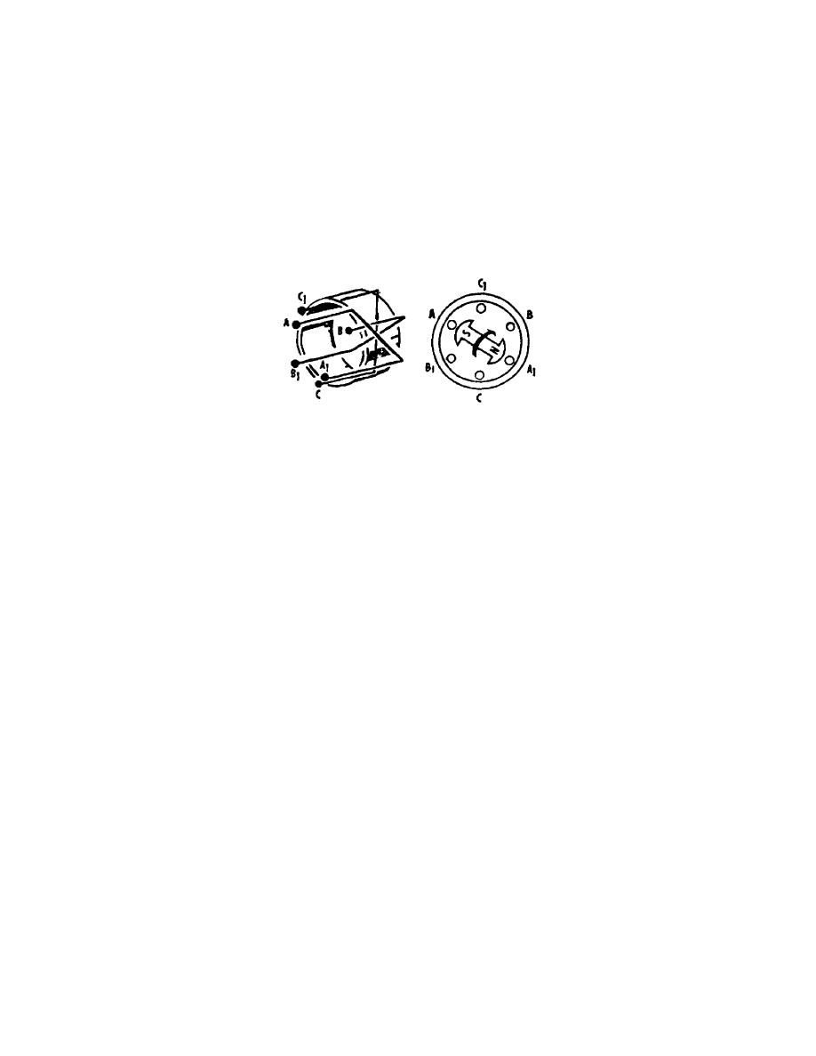
a. The single loop of wire acting as a stator winding, and the bar magnet
acting as the rotor, serve to illustrate how an AC voltage is produced in a basic
generator. When two more separate loops of wire, spaced 120 apart, are added to
our basic generator, two more separate voltages will be produced (fig 23).
Figure 23.
Three-phase operation.
b. With the S pole of the rotor directly under the A conductor the voltage
at A will be maximum in magnitude and positive in polarity. After the rotor has
turned through 120, the S pole will be directly under the B conductor and the
voltage at B will be maximum positive. Similarly, 120 later, the voltage at C
will be maximum positive. This means that the peak positive voltages at A, B, and
C in each loop of wire occur 120 apart. These loop voltage curves are shown in
figure 24.
c. When the ends of the loops of wire marked A, B, and C are connected to
the ends marked B, C, and A respectively (fig 25), a basic three-phase
"delta"-connected stator is formed. The three AC voltages available from the
delta-connected stator are identical to the three voltages previously discussed,
and may now be denoted as the voltages from B to A, C to B, and A to C, or more
simply BA, CB, and AC. An inspection of figure 25 will show the logic of this
notation. The voltage formerly called AA may now be called BA.
d. When the ends of the loops of wire marked A1, B1, and C1 are connected
together, a basic three-phase "Y"-connected stator is formed. The three voltages
available from the "Y"-connected stator may be labeled BA, CB, and AC. From figure
26, it may be seen that each of these voltages consists of the voltages in two
loops of wire added together. For example, the voltage measured from B to A
consists of the voltages in loops B1B and A1A added together. This addition yields
a voltage curve BA similar in shape and form to the individual loop voltages,
except that the voltage curve BA will be approximately 1.7 times as large in
magnitude as an individual loop voltage. The addition of the loop voltages
involves a mathematical process which will not be presented here, since it is only
necessary to remember that three AC voltages spaced 120 apart are available from
the "Y"-connected stator, as illustrated. These voltage curves will be considered
in more detail in the following paragraphs.
OS 010, 1-P12


 Previous Page
