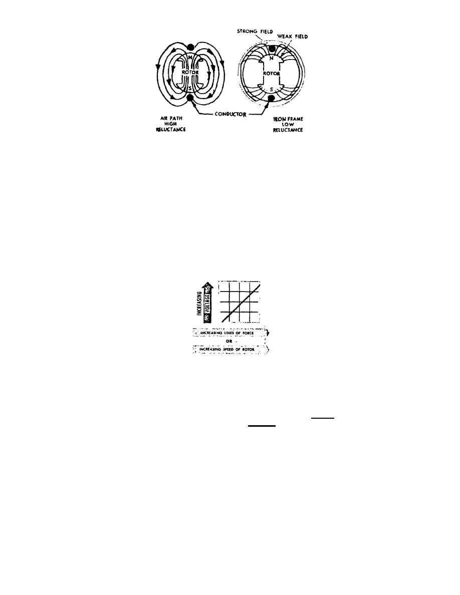
Figure 19.
Magnetic field reluctance.
d. It is important to note that a very large number of magnetic lines of
force are at the center of the tip of the magnet, whereas there are only a few
lines of force at the leading and trailing edges of the tips. Thus, there is a
strong magnetic field at the center and a weak magnetic field at the leading and
trailing edges. This condition results when the distance, called the airgap,
between the magnet and field frame is greater at the leading and trailing edges
than at the center of the magnet.
e. The amount of the voltage induced in a conductor is proportional to the
number of lines of force which cut across the conductor in a given length of time.
Therefore, if the number of lines of force are doubled, the induced voltage will be
doubled. The voltage will also increase if the bar magnet is made to turn faster,
because the lines of force will be cutting across the wire in a shorter period of
time (fig 20).
Figure 20.
Induced voltage.
f. It is important to remember that either increasing the speed of rotation
of the bar magnet, or increasing the number of lines of force cutting across the
conductor, will result in increasing the voltage. Similarly, decreasing the speed
of rotation or decreasing the number of lines of force will cause the voltage to
decrease. The rotating magnet in a generator is called the rotor, and the loop of
wire and outside frame assembly is called the stator.
6.
SINGLE PHASE GENERATOR.
a. Pictured in figure 21 are different positions of the rotor as it rotates
at constant speed. In the top portion of the illustration is a curve showing the
magnitude of the voltage which is generated in the loop of wire as the rotor
revolves. The voltage curve shows the generated voltage or electrical pressure
which can be measured across the ends of the wire, Just as voltage can be measured
across the terminal posts of a battery.
OS 010, 1-P10


 Previous Page
