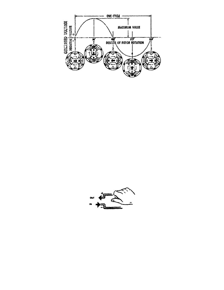
Figure 21.
Single phase.
b. With the rotor in the first position (1) there is no voltage being
generated in the loop of wire, because there are no magnetic lines of force cutting
across the conductor. As the rotor turns and approaches position (2), the rather
weak magnetic field at the leading edge of the rotor starts to cut across the
conductor and the voltage increases. When the rotor reaches position (2), the
generated voltage has reached its maximum value as shown above the horizontal line
in the illustration. The maximum voltage occurs when the rotor poles are directly
under the conductor. It is in this position that the conductor is being cut by the
heaviest concentration of magnetic lines of force.
c. It should be noted in particular that the magnitude of the voltage
varies because the concentration of magnetic lines of force cutting across the loop
of wire varies. The voltage curve shown is not a result of a change in rotor
speed, because in the illustration the rotor is considered to be turning at a
constant speed.
d. By applying the Right-Hand Rule (fig 22) to position (2), it is seen
that the direction of current in the loop of wire will be out of the top end of the
conductor and into the bottom end. Thus, the top end of the conductor will be
positive and the bottom end negative. The voltage curve which is shown above the
horizontal line represents the positive voltage at the top end of the wire loop
which is generated as the rotor turns from position (1) to position (3). As the
rotor turns from position (2) to position (3), the voltage decreases until at
position (3) it again becomes zero.
Figure 22.
Right-Hand Rule.
When the
rotor turns from position (3) to position (4), note that
e.
the N pole of the rotor is now passing under the top part of the wire loop and
the S pole under the bottom part. From the Right-Hand Rule the top end of the loop
of wire is now negative and the bottom end positive. The negative voltage at the
top end Of the loop is pictured in the illustration by
OS 010, 1-P11


 Previous Page
