Table 1.
Lubrication Instructions.
b. Frame assembly. Once the frame is completely assembled with the field
coils and everything secure, apply electrical varnish to the inside of the frame
and-field coil assembly. It is necessary to leave 0.380 inch from each end of the
frame free of varnish for installation of the end pieces. Allow to dry thoroughly
before continuing.
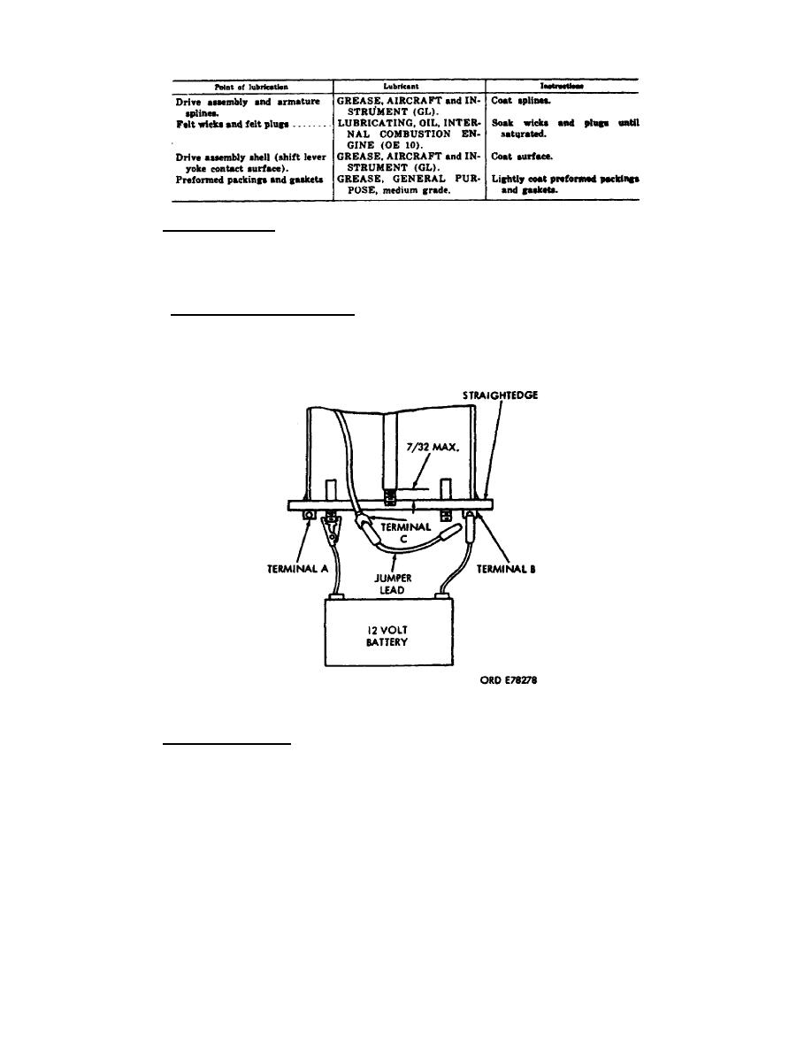
adjustment (fig 27). The solenoid is energized and the distance from the shaft
shoulder to the straightedge is measured. The self-locking nut must be adjusted
until proper alinement is achieved. Once this is done, the solenoid can be
completely assembled.
Figure 27.
Plunger adjustment.
d. Other components. The intermediate housing, commutator end head
assembly, and pinion housing are prepared for final installation on the starter.
This includes filling of the oil reservoirs, saturating the felt wicks, and
installing oil seals and preformed packings.
0S 010, 6-P22


 Previous Page
