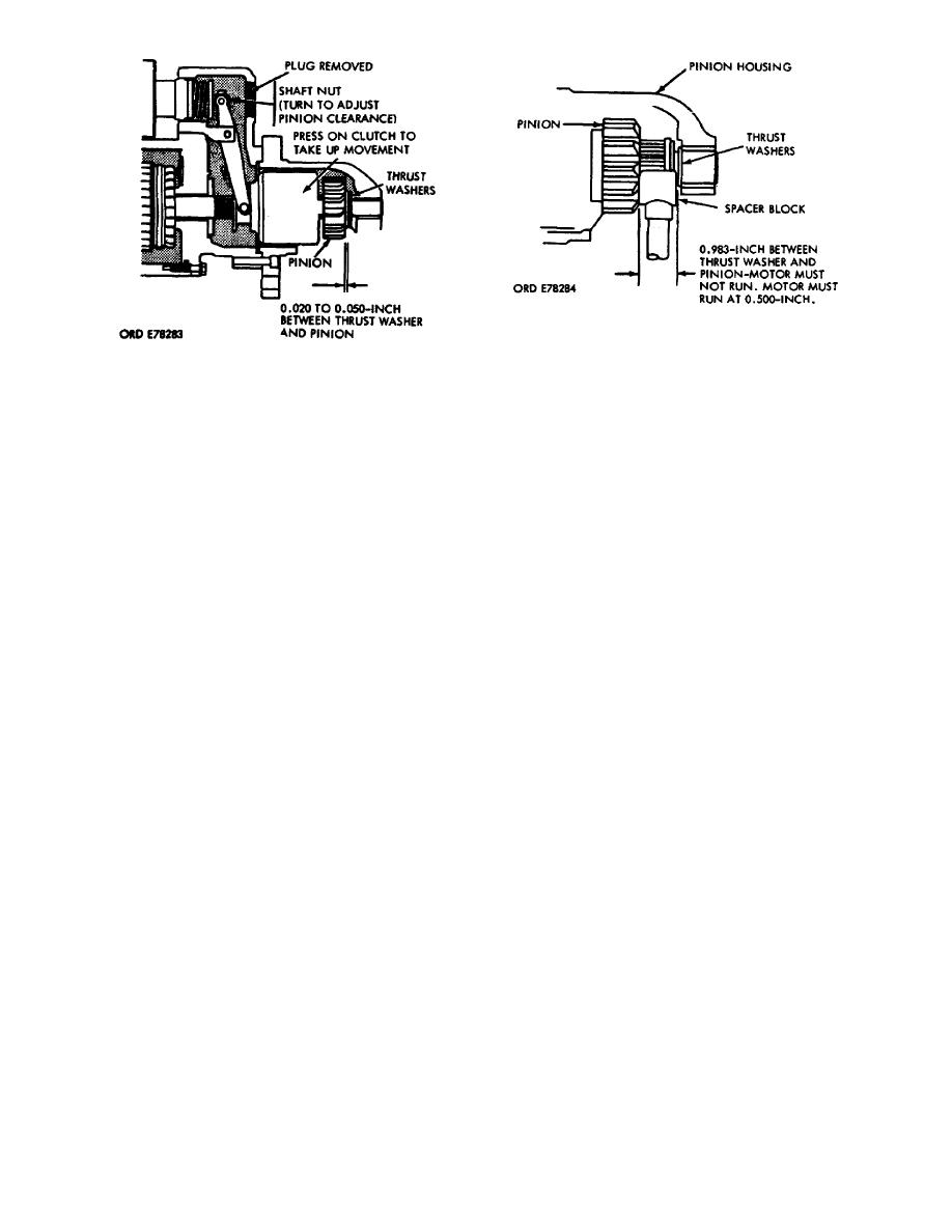
Figure 30.
Pinion clearance.
Figure 31.
Pinion block test.
i. At the completion of the clearance and block tests, restore the cables
to their normal functional connections. This completes the assembly of the starter.
SECTION IV.
TESTING
11.
TESTING. There are three types of tests used to determine starter
performance: the no load test, where the starter free runs; stall torque test,
where starter torque is measured: and a waterproof test, where the starter is
submerged in water.
CAUTION:
Never operate the starter more than 30 seconds at a time. Allow the
motor to cool for at least 2 minutes between each cranking cycle.
Overheating, caused by excessive cranking, will seriously damage the
starter motor.
a. 500-ampere test stand. The tests performed on the 500-ampere test stand
are
the NO LOAD and STALL TORQUE tests. Figure 32 shows the mounting requirements
for
stall torque testing. The starter NO LOAD or FREE RUN tests are performed with
the
starter mounted in the same manner as for the stall torque test, but without
the
torque arm.
(1) The NO LOAD test is performed to indicate the functioning of the
starter. When there is no load connected, it will run freely at a specific minimum
RPM and current drain.
(a) For the no load test, the test leads are connected between the
positive (+) field winding terminal (B, fig 33) and the ground terminal (A, fig
33). The solenoid is not energized for this test.
(b) The parallel connection to J17 and J28 on the test stand is the
input to the DC voltage meter which monitors the voltage across the starter.
(c) The DC ammeter is wired internally to indicate the starter
current. This current is controlled by knob (24), which is a variable resistance
device called a carbon pile.
OS 010, 6-P25


 Previous Page
