15.
STATOR REPLACEMENT.
a. When tests indicate an open or grounded stator or if it is mechanically
damaged, the stator must be replaced. Unsolder the three stator leads from the
splices and cut the three stator leads on both sides of the intermediate housing.
These leads should be cut as close to the housing as possible. The defective
stator may now be removed from the intermediate housing by tapping it carefully
with a soft hammer. Remove the two screws which retain the insulator and carefully
pry the insulator off of the three leads.
b. Using a small drill or a punch and hammer, remove epoxy which seals the
three leads into the housing. This must be done very carefully to avoid damage to
the housing. When all epoxy has been removed from the hole, insert the new stator
so that the three leads protrude through the housing and reinstall the fiber
insulator around the leads. Replace the two screws which secure the insulator.
Reconnect the three leads to the splices and solder them securely. Be sure to slip
the insulating sleeving over the splices when completed. Place the stator and
intermediate housing on the bench with the stator facing upward and apply epoxy
around the stator leads. Sufficient epoxy should be used to completely fill the
recess in the housing around the leads. Allow the epoxy to harden thoroughly
before reassembling the alternator.
c. After the various electrical tests have been made and defects corrected,
the alternator may be reassembled.
d. If the bearings are to be replaced, special care must be used to avoid
damage. When pressing a bearing onto the shaft, apply pressure to the inner race
with a suitable tool. When pressing a bearing into a housing, press only on the
outer race. This will avoid applying force through the bearing balls, which could
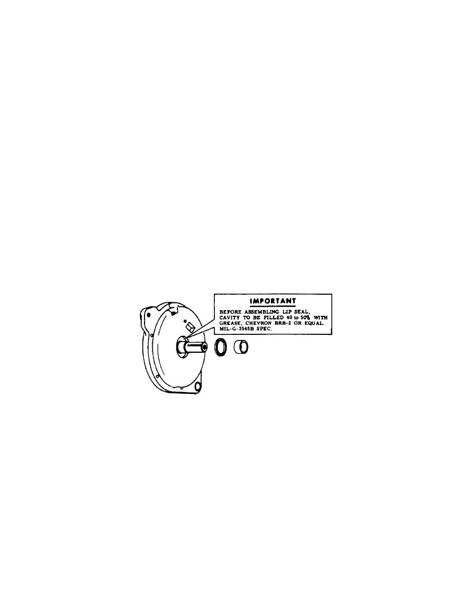
damage the bearing. When replacing the lip seal, pack with grease as shown in
figure 12.
Figure 12.
Stator housing.
16.
REASSEMBLY.
a.
Install new bearing on antidrive end of rotor and press housing onto
bearing.
b. Install rotor and housing assembly into stator and intermediate housing.
When installing the rotor, it is necessary to use a special tool to avoid damage to
the seal. Details of the tool and installation are shown in figures 13, 14, 15,
and 16. Insert the tapered end of the tool into the intermediate housing seal from
the drive end or brush holder side of the housing. Be sure the surface of the tool
that enters the seal is free from nicks and burs, which would damage the seal.
Carefully slide the rotor into
OS 010, 2-P10


 Previous Page
