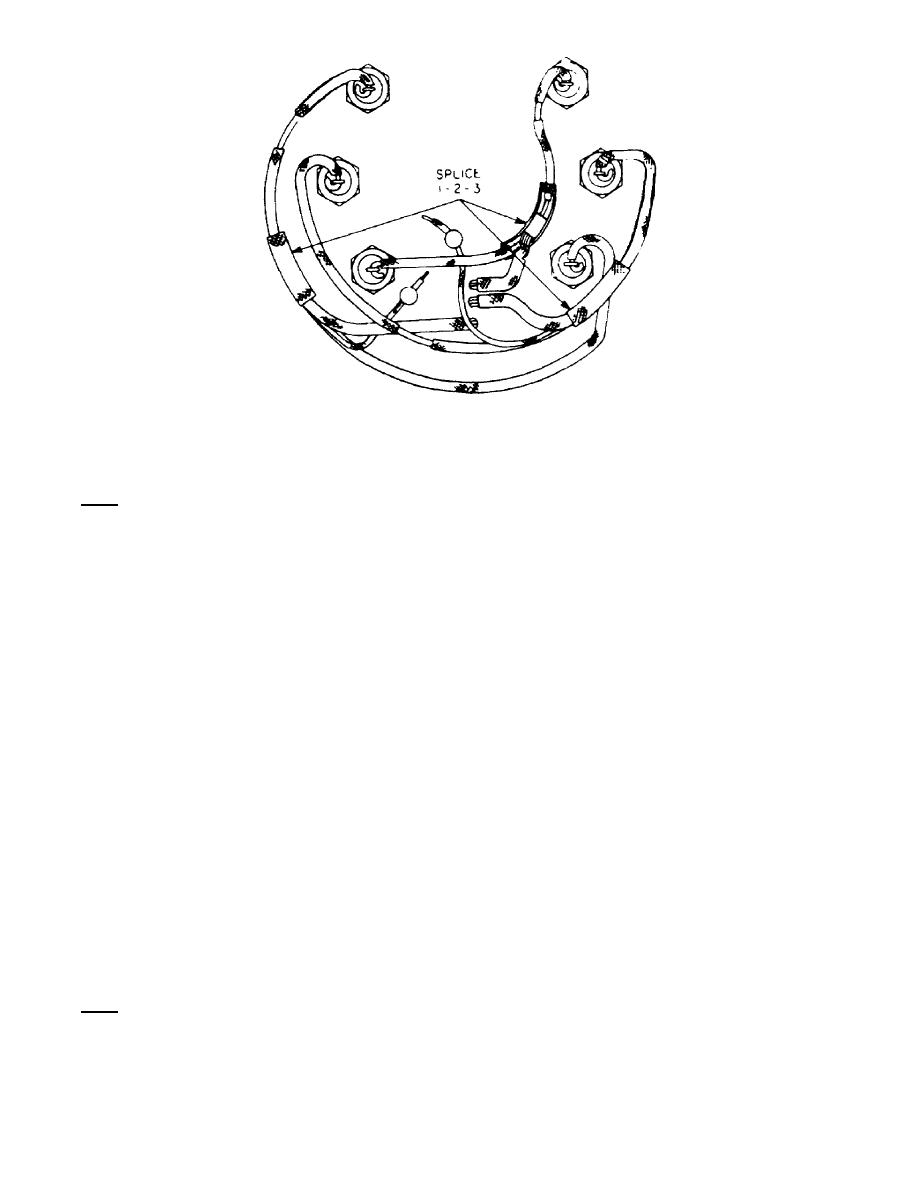
Figure 10.
9. STATOR CONTINUITY TEST.
Note. - The following ohmmeter connections should all obtain a zero reading if
stator and all connections are good.
a.
One ohmmeter lead splice to 1, the other to splice 2.
b.
One ohmmeter lead to splice 2, the other to splice 3.
c.
One ohmmeter lead to splice 3, the other to splice 1.
10.
STATOR GROUND TEST.
a.
Connect one ohmmeter lead to the generator housing.
b. Touch the other ohmmeter lead to splices 1, 2, and 3 in succession while
observing meter.
c. A reading of less than infinity indicates faulty stator insulation
(grounded stator).
11.
ROTOR RESISTANCE TEST. Connect one ohmmeter lead to a slipring; the
other ohmmeter lead to the remaining slipring. Resistance, for rotor to be
serviceable, must be 7.0 to 7.9 ohms.
12.
ROTOR GROUND TEST. Connect one ohmmeter lead to either of the
sliprings and the other lead to the rotor shaft. For rotor to be good, resistance
must be greater than 10,000 ohms.
13.
CONTINUATION OF DISASSEMBLY.
a. The voltage regulator may be removed from the drive end housing by
removing four Allen screws.
Note. - The regulator also serves as a bearing retainer and must be removed when
replacing the drive end bearing (B, foldout 1).
OS 010, 2-P8


 Previous Page
