• Home
  • Download PDF
  • Order CD-ROM
  • Order in Print

Home > Ordnance Documents and other related manuals > > Figure 44. APU Terminal B. Wire 65 at the Control Box Harness.
Figure 43. Terminal C, Lead 65, APU Main Harness Plug
Figure 46. APU Wiring Harness Lead 65 to Starter Relay.

Troubleshooting the Auxiliary Power Unit (APU) M992 carrier, Ammunition,
Page Navigation
  35    36    37    38    39  40  41    42    43    44    45  

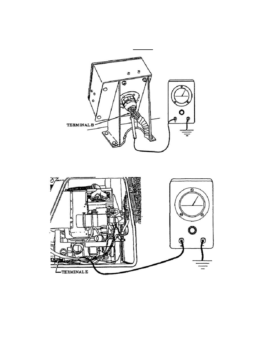
GENerator switch to the ON position, and then hold the PREHEAT and START
switches ON (Figure 45).  If no voltage is indicated, repair or replace the
main harness lead 65 between the APU compartment receptacle and the APU
control  box  plug  as  illustrated  in  TM  9-2350-267-20.
If  voltage  is
indicated during this test, proceed to Test 12.
Figure 44.
APU Terminal B, Wire 65 at the
Control Box Harness.
Figure 45.
APU Terminal E, Lead 65.
40
OD1702


Western Governors University

< Previous Page
Index ^
Next Page >

Privacy Statement
Press Release
Contact

© Copyright Integrated Publishing, Inc.. All Rights Reserved. Design by Strategico.