

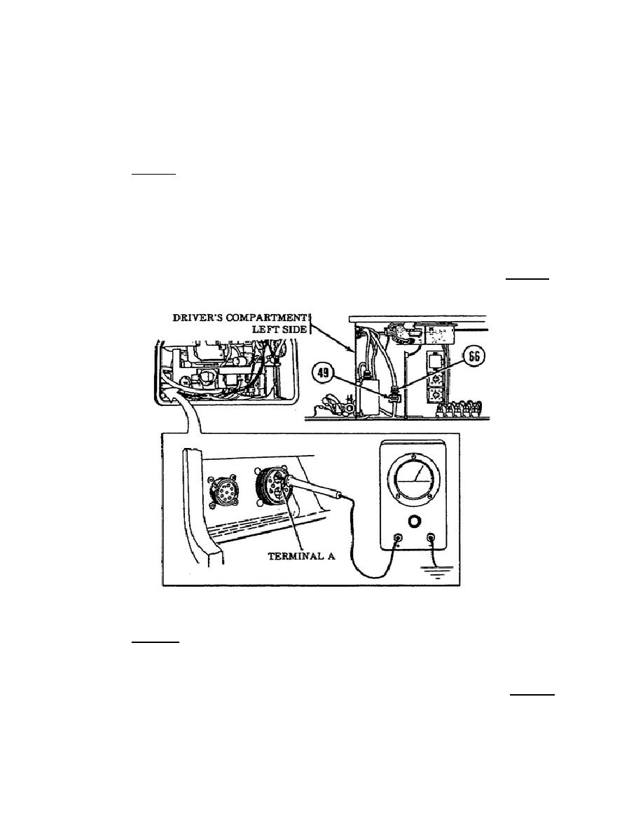
If voltage is indicated, repair or replace harness lead 66 to the
APU wall-mounted receptacle IAW TM 9-2350-267-20. If no voltage
is indicated, troubleshoot the main power harness IAW TM 9-2350-
267-20 (Figure 37).
NOTE:
If main cargo compartment wiring harness (12330252) is defective,
notify Support Maintenance.
o
Test 2.
If voltage was indicated when testing terminal A, set
the MASTER switch to the OFF position.
Reconnect the main
harness connector to the APU wall-mounted receptacle and remove
the APU engine door panel. Test terminals N and P by placing the
multimeter red probe on terminals N and P and placing the black
probe on a good ground (Figure 38). Set the MASTER switch to the
ON position. If no voltage is indicated, lead N must be repaired
or replaced as outlined in TM 9-2350-267-20.
If you obtain a
voltage reading when testing terminals N and P, then Test 3 must
be accomplished.
Figure 37.
APU Wall-mounted Receptacle and Leads 49 and 66.
o
Test 3.
Since a voltage reading was obtained when testing
terminals N and P, place the multimeter red probe on terminal P
and the black probe to a good ground (Figure 39). If no voltage
is indicated, lead P must be repaired or replaced. If voltage is
indicated after testing terminal P, then proceed to Test 4 and
conduct a test on terminal 487.
35
OD1702


 Previous Page
