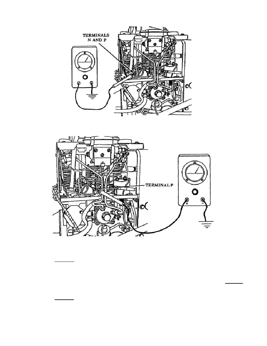
• Home
  • Download PDF
  • Order CD-ROM
  • Order in Print

Home > Ordnance Documents and other related manuals > > Figure 38. APU Treminal N And P.
Figure 37. APU Wall -Mounted Receptacle ald Leads 49 and 66.
Figure 41. APU Terminal D, Lead 487.

Troubleshooting the Auxiliary Power Unit (APU) M992 carrier, Ammunition,
Page Navigation
  31    32    33    34    35  36  37    38    39    40    41  

Figure 38.
APU Terminals N and P.
Figure 39.
APU Terminal P.
o
Test  4.
Do  a  voltage  test on  terminal  487  by  placing the
multimeter red probe on terminal 487 and placing the black probe
on a good ground (Figure 40).
If no voltage is indicated, the
preheat solenoid is defective and Support Maintenance must be
notified.  If voltage was indicated during this test, then Test 5
must be accomplished.
o
Test 5.
With the MASTER switch in the OFF position, locate
terminal D, lead 487, in the APU harness plug.
36
OD1702


Western Governors University

< Previous Page
Index ^
Next Page >

Privacy Statement
Press Release
Contact

© Copyright Integrated Publishing, Inc.. All Rights Reserved. Design by Strategico.