

o
Test 17.
Use this test to determine if voltage is present at
generator terminal A. Set the MASTER switch to the OFF position.
Place the red multimeter probe on generator terminal A and place
the black probe to a good ground. Now set the MASTER switch to
the ON position and hold the PREHEAT and STARTER switches ON
(Fig. 50). If no voltage is indicated, repair or replace lead S
between generator terminal A and the diode as outlined in TM 9-
2350-267-20. If voltage is indicated, proceed to Test 18.
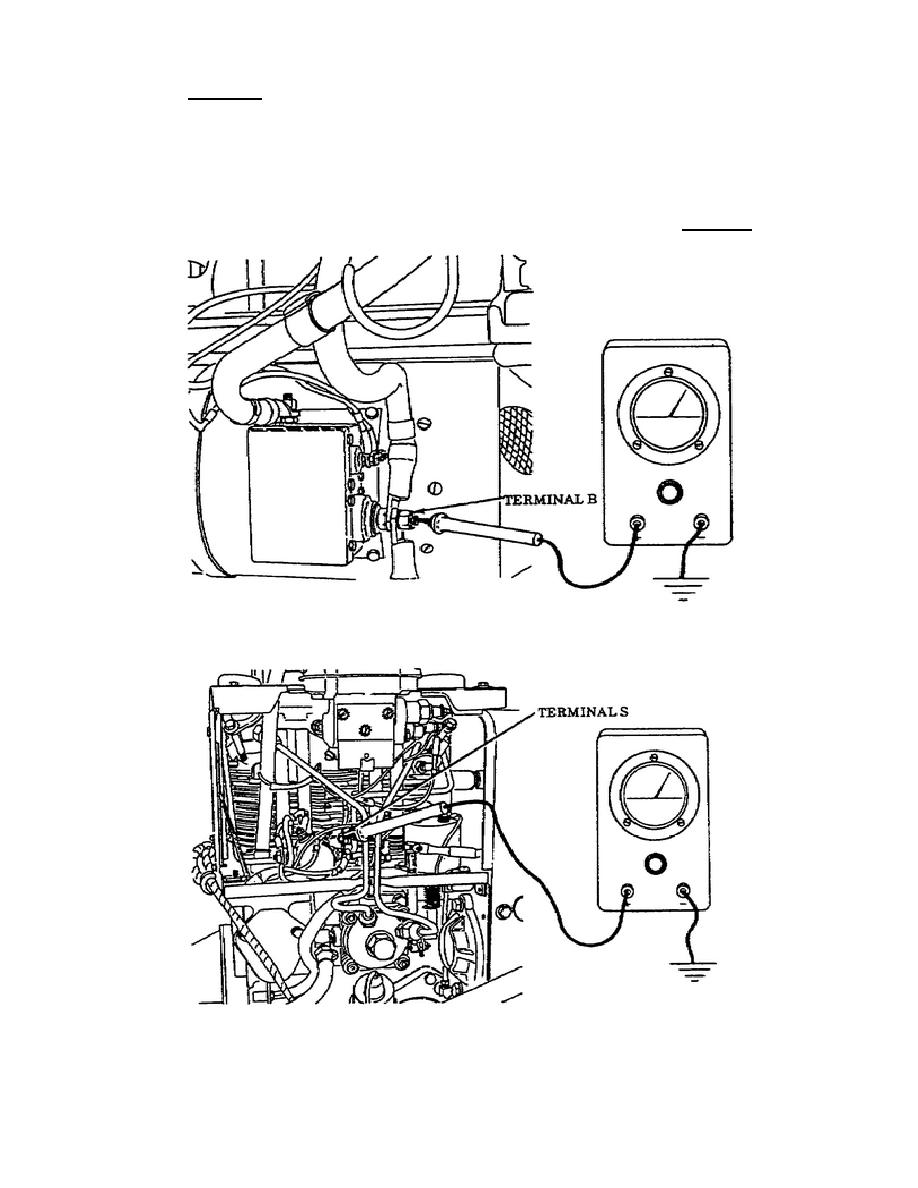
Figure 48.
APU Generator Terminal B.
Figure 49.
APU Terminal S, Preheat Solenoid.
43
OD1702

 Previous Page
