

M2/M3 BFV: FIRE SUPPRESSION SYST - OD1607 - LESSON 2/TASK 1
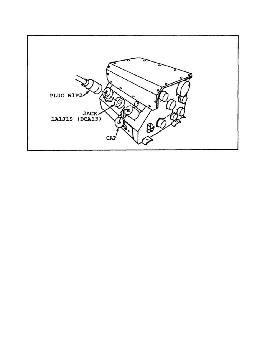
FIGURE 25.
VEHICLE DISTRIBUTION BOX (DCA 13).
(5) Push the VTM circuit breaker (refer to figure 24 on page
33) to ON.
Three situations could arise.
If all is working well,
the display should read 8.8.8.8. and then - - - - (four dashes). If
the display does not read 8.8.8.8 and - - - - (four dashes)
consecutively, but is not blank, the VTM is faulty and should be
written up as such on DA Form 2404.
If the display is blank, the
procedures for performing diagnostic troubleshooting of the STE-
M1/FVS (VTM only) for a blank display can be found, when needed, on
page 3-903 of TM 9-2350-252-20-1-1.
These procedures will not be
covered in this subcourse.
(6) If the display reads correctly, perform the VTM confidence
check using the instructions on the flip cards on the VTM.
If the
VTM confidence check does not pass, the VTM confidence test
diagnostic troubleshooting procedures can be found, when needed, on
page 3-910 of TM 9-2350-252-20-1-1.
These procedures will not be
covered in this subcourse.
(7) Dial TEST SELECT to 62, then press and release the TEST
button.
If DCA13 does not appear on the VTM display, troubleshoot
the VTM for this malfunction using the procedures in TM 9-4910-751-
14-1.
35


 Previous Page
