inverter is shown in figure 1-31C.
Inverters, when placed at the
input or output of the basic gates, may provide a variety of
When the inverter is used with the basic gate, only
the small circle of the inverter symbol is used in the schematic
diagram.
Figure 1-31D shows an AND gate with an inverter at its
output. The result is a NAND gate. Similarly, placing an inverter
at the output of an OR gate will produce a NOR gate (figure 1-31E).
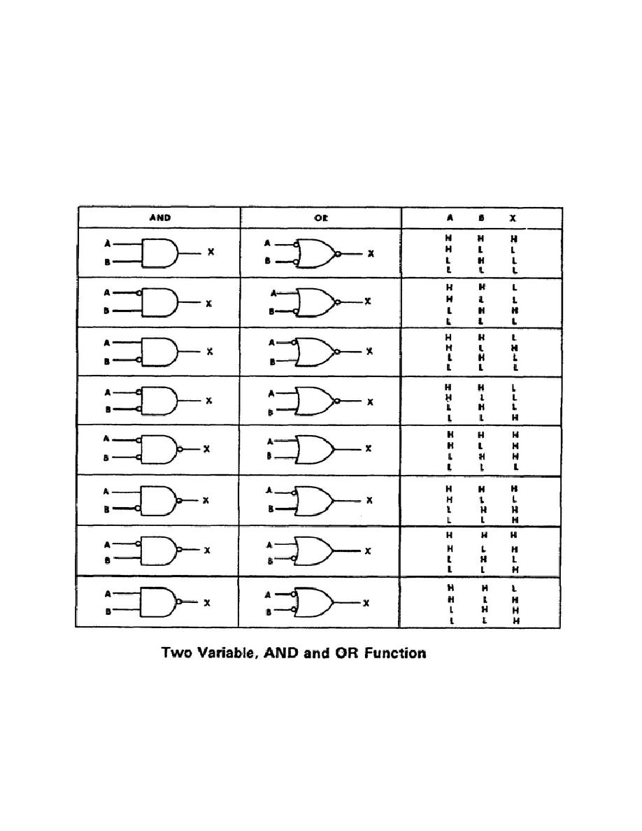
Figure 1-32 shows the variations of two-variable AND gates and OR
gates, and the resulting "truth table" for their output.
Figure 1-32.
Two-Variable Truth Table.
20
OD1725


 Previous Page
