relay and re-route the electrical signals.
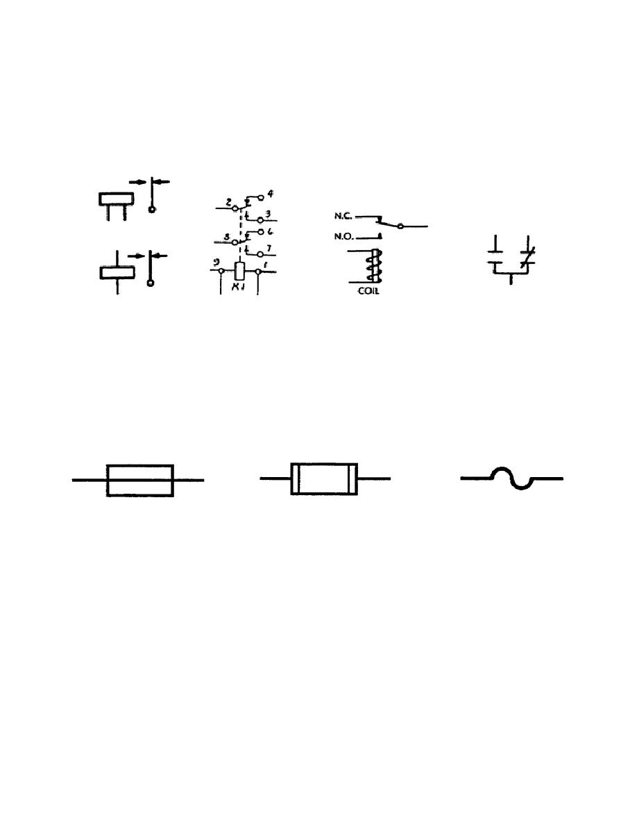
Relays may be indicated
in schematics only by their coil and its energizing source, only by
the contacts used by the particular circuit, or by both.
Contacts
are normally shown in the position with the relay de-energized,
unless otherwise indicated. Figure 1-17 illustrates some methods of
representing relays symbolically. Relays are labeled with the letter
"K."
Figure 1-17.
Relays.
c. Fuses. Fuses are used to protect circuits from overvoltage or
overcurrent
conditions.
Unlike
circuit
breakers,
which
are
electromechanical, fuses are thermally sensitive.
When the circuit
becomes overloaded, the metal alloy of the fuse melts (opens) and
removes the power source from the equipment.
Fuses are designed to
meet the requirements of the circuits they are protecting.
The
symbols used for fuses are shown in figure 1-18. Fuses are labeled
with the letter "F."
Figure 1-18.
Fuses.
d. Plugs, Jacks, and Test Points. Plugs and jacks are generally
used to connect the equipment to some external device, or to
interconnect circuits and components within the equipment. Plugs and
jacks may be single conductor or multiconductor.
They may be
permanent or removable, shielded or unshielded.
Jacks and plugs
often provide a convenient means to check or test critical signals.
This provides an extremely useful function in troubleshooting. Where
it is impossible or impractical to check a signal at a jack or plug,
circuits are often designed to provide test points.
These test
points may be internal to the circuit or tapped off and provided at
an external point. Figure 1-19 illustrates some typical symbols used
for jacks, plugs, and test points. Jacks are labeled with the letter
"J"; plugs with the letter "P"; and test points with the letters
"TP." With
12
OD1725


 Previous Page
