(7) Reverse 1 range (fig. A-6).
The reverse ranges are the
only ranges that do not require the forward clutch engagement.
The
transmission must have the fourth and first clutches applied for this
range.
Applying the fourth clutch rotates the sun gear shaft assembly (with
the front and center sun gears splined to it) at range input speed.
The application of the first clutch prevents the rear ring gear from
rotating.
The center sun gear rotates the center carrier pinions
which rotate the center ring gear in an opposite direction.
The
center carrier is splined to the front ring gear which is splined to
the rear carrier.
The reverse direction of the center ring gear
rotates the rear sun gear. This causes the rear planetary pinions to
drive the rear carrier, in a reverse direction, with the stationary
ring gear. The compounding action of the center and rear planetaries
gives rotation with a speed reduction to the center carrier, which is
splined to the range output.
(8) Reverse 2 range (fig. A-7).
To produce this range, the
transmission applies the fourth clutch, which rotates the sun gear
shaft assembly (with the front and center sun gears splined to it) at
range input speed, and the second clutch (which prevents the front
carrier from rotating).
The rotating front sun gear rotates the front carrier pinion (whose
carrier the second clutch has anchored against rotation).
This
rotation causes the front carrier pinions to the drive the front ring
gear in a reverse direction.
The front ring gear (splined to the
rear carrier assembly) causes the rear carrier assembly to rotate
which drives the range output gear.
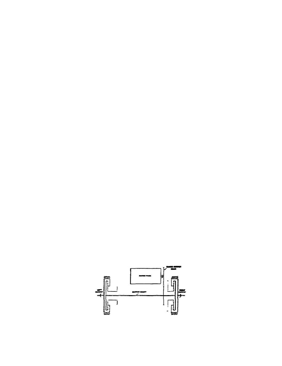
(9) Range output and combining planetaries torque path (fig.
1-15).
The range output gear transmits power to a driven gear
splined to the output shaft.
The output shaft, attached through
splines, drives the ring gear in each combining planetary. The ring
gear serves as the input (driven by the output shaft) to each
combining set; the sun gear is the reaction member making the carrier
the output to the final drives.
Figure 1-15.
Range Outlet Torque Path.
23
OD1710


 Previous Page
