

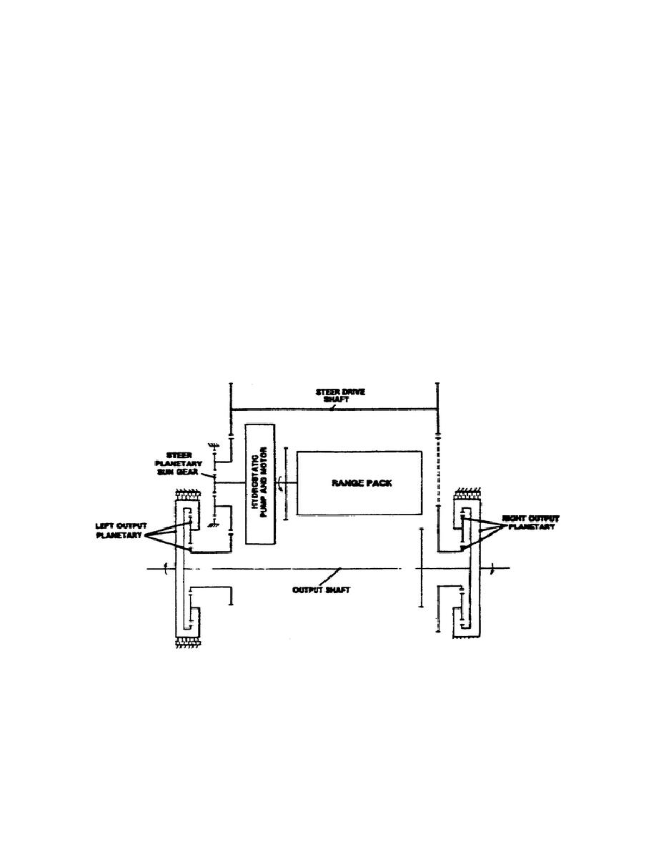
(10) Pivot steer torque path (fig. 1-16).
(a) Torque path to the left output.
Through splines, the
sun gear of the hydrostatic steer planetary attaches to the
hydrostatic motor. With the sun gear as the input and the ring gear
held stationary, the carrier becomes the output of the hydrostatic
motor planetary set.
The planetary carrier bolts to the gear that drives a second gear,
splined to the left output sun gear shaft.
The sun gear shaft
rotates in the opposite direction of the hydrostatic motor.
Since
the output sun serves as the input and the ring gear as the reaction
member, the carrier becomes the output to the final drive.
(b) Torque path to the right output.
The driven gear,
bolted to the steer planetary carrier, drives the steer drive shaft,
which in turn drives the right combining planetary sun gear.
This
sun gear rotates the same direction as the hydrostatic motor (or
opposite direction of the left sun gear). Since the sun gear serves
as the input, and the ring gear serves as the reaction member, the
carrier serves as the output to the final drive.
Figure 1-16.
Pivot Steer Torque Path.
This completes part A of this lesson.
This lesson continues with
part B, the transmission hydraulic system.
24
OD1710


 Previous Page
