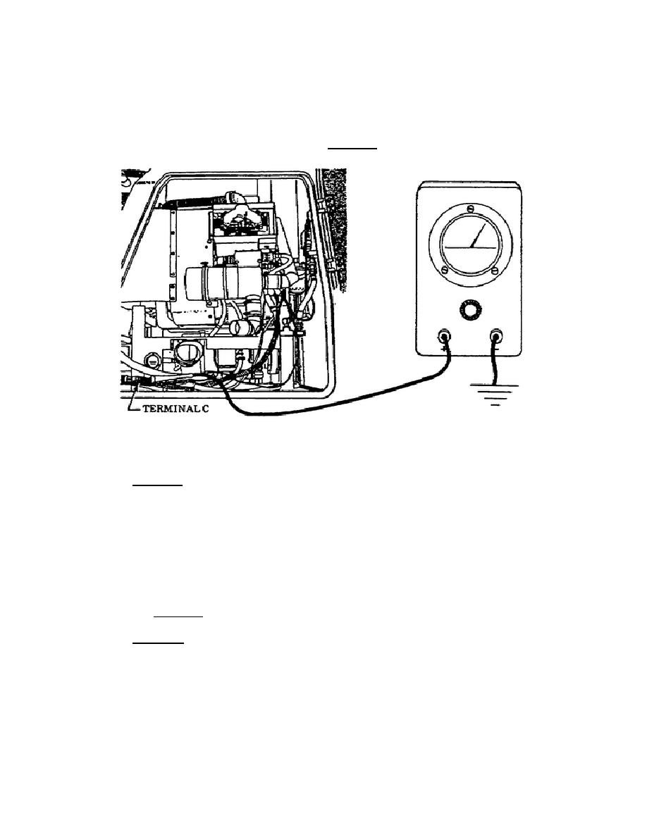
Set the MASTER switch to the ON position, the APU GENerator
switch to the OFF position, and the PREHEAT switch to the ON
position (Figure 43). If no voltage is indicated, lead 65 from
the preheat solenoid to the harness plug must be repaired or
replaced as outlined in TM 9-2350-267-20.
If voltage was
indicated during this test, a voltage test of terminal B, wire 65
must be done as outlined in Test 10.
Figure 43.
Terminal C, Lead 65, APU Main
Harness Plug.
o
Test 10. This test requires you to do a voltage test on terminal
B, wire 65, of the APU control box harness.
Ensure the MASTER
switch is in the OFF position. Probe through the insulation of
terminal B, wire 65 with the multimeter red probe and place the
black probe on a good ground. Now set the MASTER switch to the
ON position, the APU GENerator switch to the OFF position, and
hold the PREHEAT switch in the ON position (Figure 44).
If no
voltage is indicated, repair or replace lead 65 between the APU
connector receptacle terminal C and the APU control box plug,
terminal B. If voltage was indicated during this test, proceed
to Test 11.
o
Test 11.
Use this test to make a voltage check at terminal E,
lead 65, of the APU compartment main harness plug. Be sure the
MASTER switch is in the OFF position. Locate terminal E, lead 65
and probe through the insulation of terminal E lead 65 wire with
the multimeter red probe.
Place the black probe on a good
ground.
Now set the MASTER switch to the ON position, set the
APU
39
OD1702


 Previous Page
