o
Test 6. To accomplish this test, turn the MASTER switch to the
OFF position. Now remove the APU control box as outlined in TM
9-2350-267-20.
Do NOT disconnect the control box harness.
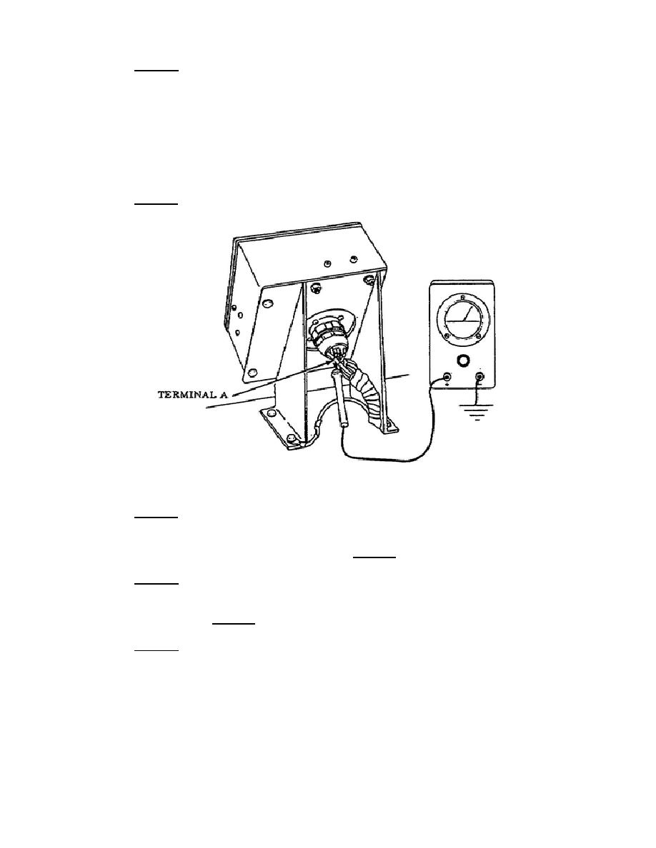
Locate the APU control box connector lead 487 terminal A. Probe
through the insulation of terminal A wire 487 with the multimeter
red probe and ground the black probe. Set the MASTER switch to
the ON position. If no voltage is indicated, repair or replace
harness lead 487 from the APU compartment connector to the APU
control box as outlined in TM 9-2350-267-20 (Figure 42).
If
voltage was indicated during this test, you must then go to
Test 7 and perform a test of the APU control box.
Figure 42.
APU Lead 487, Terminal A.
o
Test 7. This test requires a continuity test be conducted on the
APU voltage control box as outlined on pages 26 and 27 of this
subcourse.
If the APU control box is working properly and the
APU still will not crank, then Test 8 must be accomplished.
o
Test 8. This test requires you to do a voltage test on preheat
solenoid terminal 65 and R. Refer to page 25 of this subcourse
to accomplish this test.
If voltage was indicated during this
test, then Test 9 must be accomplished.
o
Test 9. This test requires you to do a voltage test at terminal
C, lead 65, in the APU main harness plug. Set the MASTER switch
to the OFF position.
Probe through the insulation of terminal
lead 65 wire with the multimeter red probe and place the black
probe on a good ground.
38
OD1702


 Previous Page
