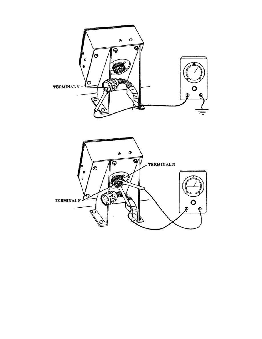
Figure 15.
APU Control Box Harness - Terminal N.
Figure 16.
APU Control Box Receptacle - Terminal N and F.
The test for continuity in the FUEL SHUT OFF switch circuitry is completed
and the meter indicated 0 ohms. Another test of the main harness connector
at the APU wall is required. This test is accomplished by disconnecting the
main harness connector at the APU wall.
Set the MASTER switch to the ON
position and place the multimeter red probe on the wall-mounted connector
terminal pin B and ground the black probe. Set the FUEL SHUT OFF switch to
the ON position. If no voltage is indicated, repair or replace harness lead
421 from the APU wall-mounted connector to the APU control panel. Refer to
Figure 17 when performing this test.
17
OD1702


 Previous Page
