

ELECTRONIC PRINCIPLES - OD1647 - LESSON 1/TASK 3
components of the input signal are coupled to the amplifier
input.
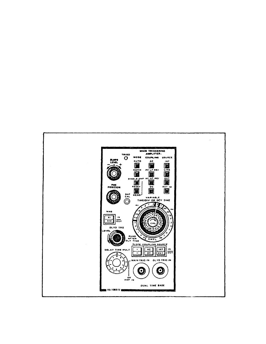
(3) DUAL TIME BASE Front Panel (figure 99).
(a) LEVEL Potentiometer. Provides for selection of the
amplitude point, on the trigger signal at which triggering
occurs.
(b) SLOPE Switch. Provides for selection of either the
positive or negativegoing slope of the trigger signal on which
to trigger.
(c) TRIG'D Indicator. Lights to indicate that the main
sweep is triggered and will produce a display with the correct
setting of the INTENSITY and POSITION controls.
FIGURE 99. DUAL TIME BASE CONTROLS.
142

 Previous Page
