

ELECTRONIC PRINCIPLES - OD1647 - LESSON 1/TASK 3
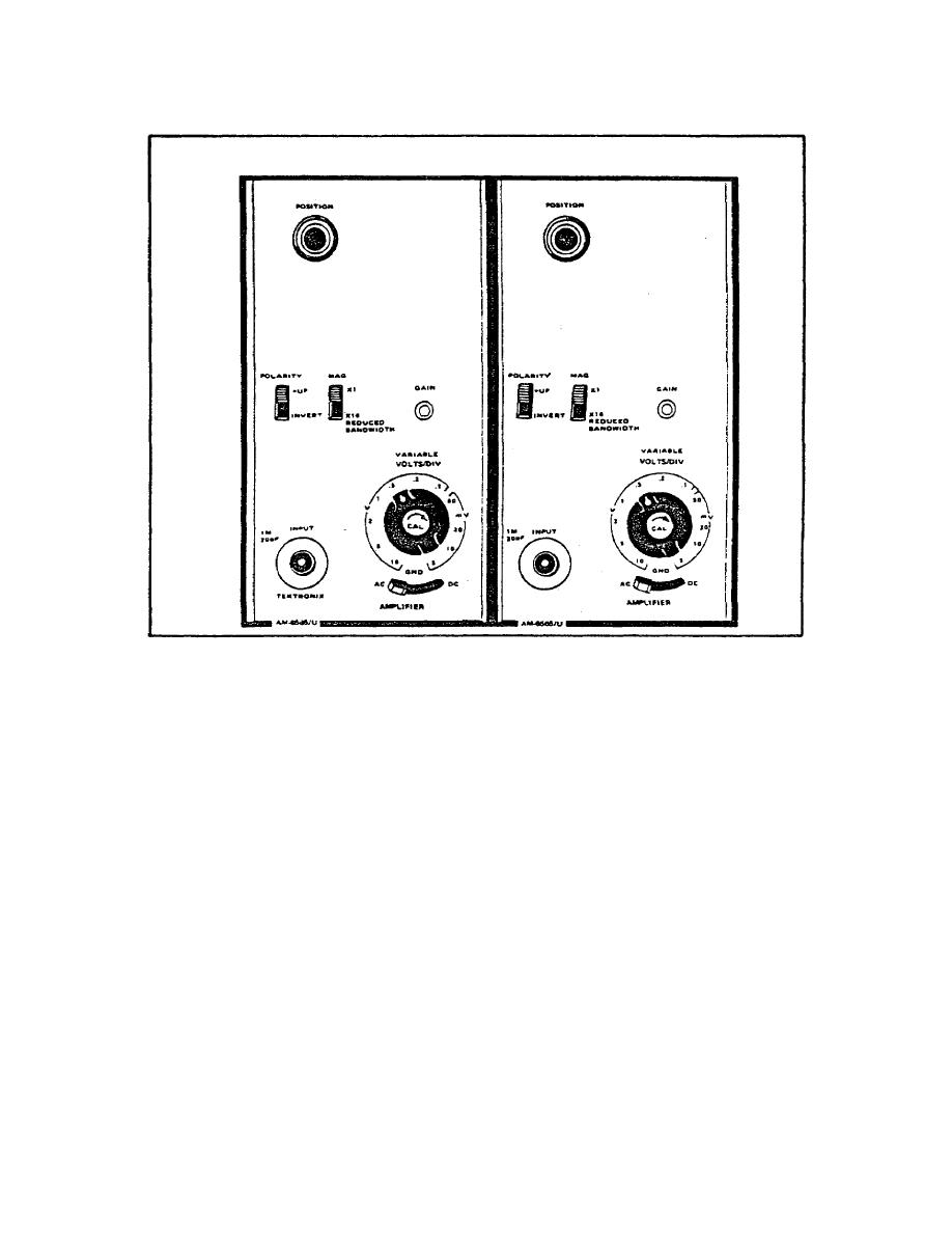
FIGURE 98. VERTICAL AMPLIFIER CONTROLS.
(e) Input Connector. Provides for connecting the amplifier
input signal cable.
(f) VOLTS/DIV Switch. Provides for selecting the calibrated
deflection factors From 5 millivolts per division to 10 volts
per division in 11 steps, in 1, 2, 5, ..... sequence.
(g) VARIABLE Potentiometer Switch. Provides for
continuously variable uncalibrated settings (up to 2.5 times)
between the calibrated deflection factor steps. Extends the
range to 25 volts per division or more.
(h) AC/GND/DC Switch. Provides for selecting the input
coupling mode. In the AC position, the input signal is
capacitively coupled to the amplifier input with the dc
component blocked. In the GND position, the amplifier input is
grounded while maintaining the same input signal load (provides
the charge path for the ac coupling capacitor to precharge the
input circuit before switching to ac). In the DC position, all
141


 Previous Page
