PRIN. OF DRAFTING AND SHOP DRAWINGS - OD1641 - LESSON 1/TASK 3
e. Isometric Dimensions.
Isometric drawings may be dimensioned by using either
the aligned system or the unidirectional system.
Regardless of the system used, the leader lines must be drawn in the same isometric
plane as the surface they are defining. The guidelines for the dimensions in the
aligned system are drawn parallel to the edge being defined, while the guidelines
for the unidirectional system are always horizontal.
Figure 53 (on the previous
page) is another example of the unidirectional system.
The numbers are drawn
either 1/8 or 3/16 inch in height in both systems.
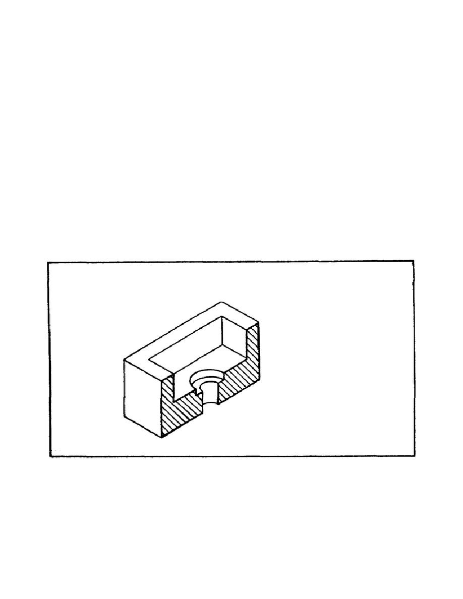
f. Isometric Sectional Views.
Isometric sectional views are used for the same
reasons that orthographic sectional views are used, to clarify objects by exposing
important internal surfaces that would otherwise be hidden from direct view.
Figure 54 shows a full isometric sectional view and a half isometric sectional
view.
Note that, as with orthographic sectional views, hidden lines are omitted
and the cross-hatching lines are drawn medium to light in color, 3/32 apart at an
inclined angle. Isometric sectional views do not require a defining cutting plane
and are usually presented as individual pictures with no accompanying reference
drawing. Dimensions are placed on an isometric sectional view in the same way they
are for regular isometric drawings.
FIGURE 54.
ISOMETRIC SECTION CUT.
63


 Previous Page
