Lesson 3/Learning Event 4
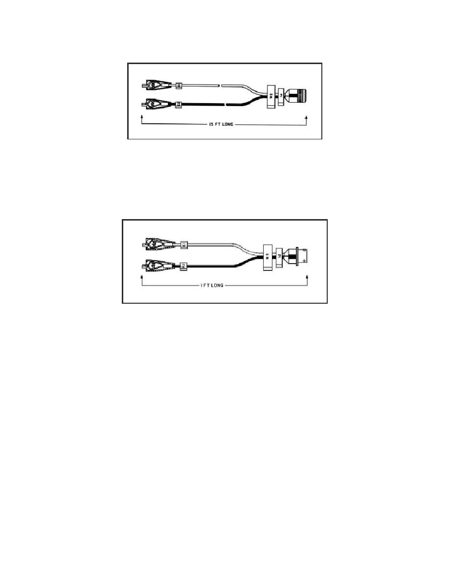
FIGURE 54. TEST PROBE CABLE W2.
Used for general and special measurements. It is used for measuring voltages, frequency, resistance,
and continuity; and also for the first-peak series and compression unbalance tests. W2 is divided
into two color coded leads, red for E1 and black for E2. Test clips E1 and E2 of W2 attach to
points on the equipment being tested.
FIGURE 55. IGNITION ADAPTER CABLE W3.
Used in measuring dwell angle, points voltage, engine RPM, and power tests. W3 is divided into
two color-coded leads; red for E1 and black for E2.
99


 Previous Page
