Lesson 3/Learning Event 4
PRINCIPLES OF OPERATION
This section describes the principles of operation for the STE/ICE VTM, cables, and accessories.
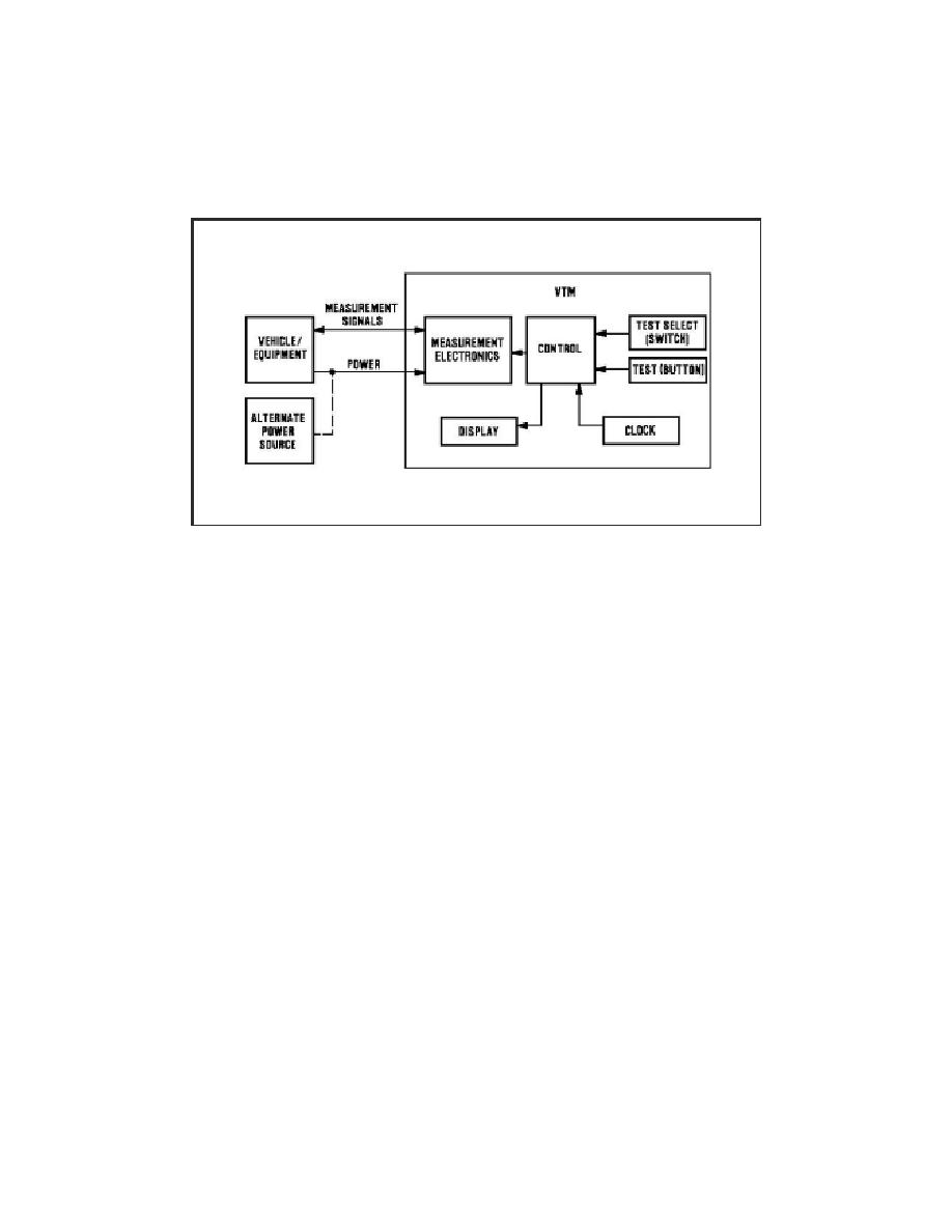
Block diagrams show power, control, and display functions.
FIGURE 58. OPERATIONAL DIAGRAM.
Power is supplied to the VTM from the vehicle/equipment battery or an alternate power source.
Measurement information is sent to the VTM and is compared to values stored in its memory.
Setting the TEST SELECT switches tells the VTM which measurement procedure to do.
Pressing and releasing the TEST button tells the VTM to perform the measurement procedure.
The VTM display shows the results in the unit being measured (volts, RPM, PSI, and so forth) or
as a PASS/FAIL message.
102


 Previous Page
