

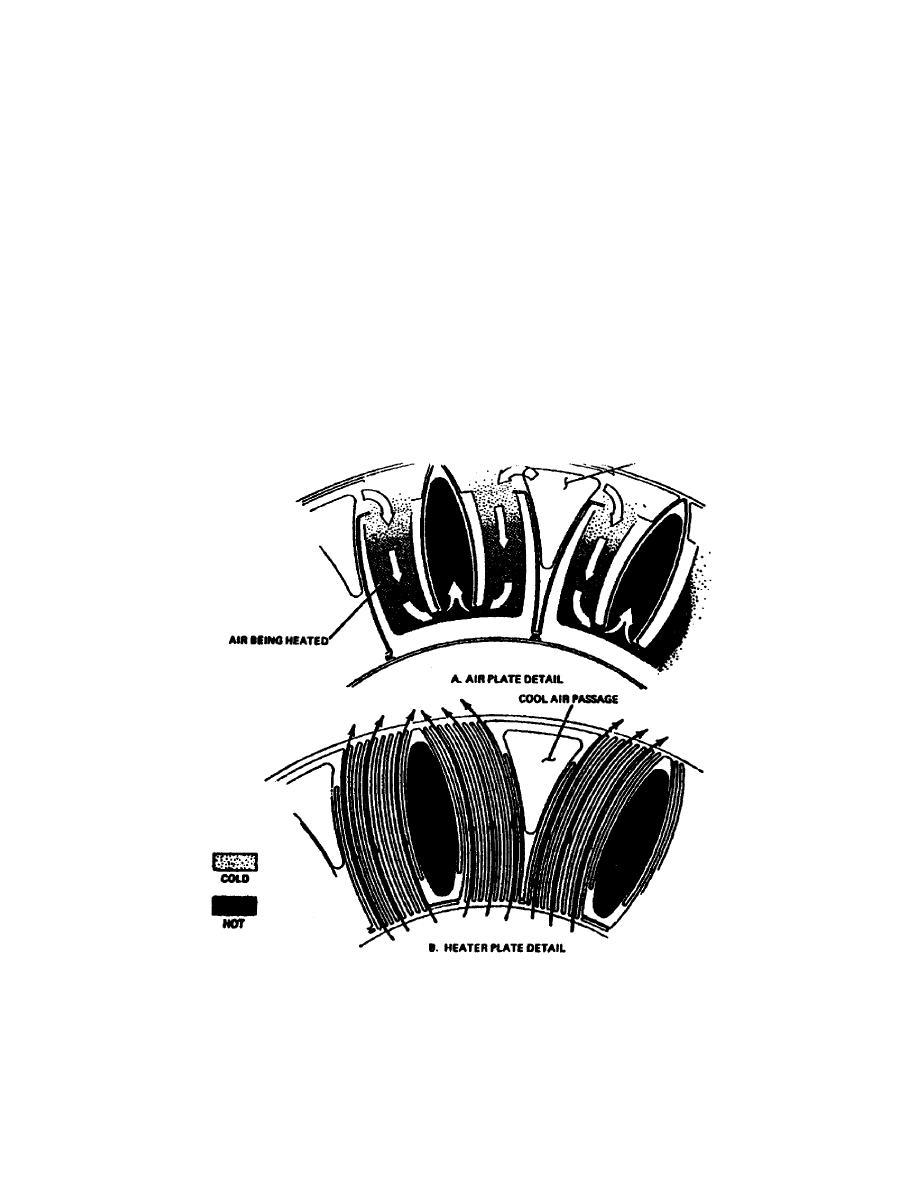
The air plate (Figure 124, A) is constructed with a flat pathway between the
oval and triangular ports. The incoming cool air passes down the triangular
ports and enters a passage between triangular and oval ports. As the air
passes through the pathways, it is heated by exhaust gases exiting above and
below the pathway. The exhaust gas enters the middle of the recouperator,
passes through heater plates (Figure 124, B), and exits the outside of the
unit, giving up heat to the cool air in the process. The benefits obtained
from the use of a recouperator are listed below.
(a) High thermal efficiency.
(b) Lower specific fuel consumption.
(c) Lower exhaust temperature.
Basically, the only disadvantage to this system is the additional weight of the
unit to the vehicle.
Figure 124. Recouperator Plate Detail.
35
OD0610

 Previous Page
