2. The steel spindle is actually the unthreaded part of the screw.
It the spindle that advances or retracts to open or close the open side of the U-
frame. The spindle bearing is a plain bearing and a part of the frame.
3. The hollow barrel extends from this bearing, and on the side of
the barrel is the micrometer scale, which is graduated in tenths of an inch, which
are in turn divided into subdivisions of 0.025 inch. The end of the barrel
supports the nut which engages the screw. This nut is slotted and its outer
surface has a taper thread and a nut which make it possible to adjust the diameter
of the slotted nut within limits to compensate for wear.
4. The thimble is attached to the screw and is a sleeve that fits
over the barrel. The front edge of the thimble carries a scale broken down into 25
parts. This scale indicates parts of a revolution, where the scale on the barrel
indicates the number of revolutions. The thimble is connected to the screw through
a sleeve that permits it to be slipped in relation to the screw for the purpose of
adjustment. The inner sleeve is sweated to the screw. The outer sleeve is clamped
to the inner one by the thimble cap. Loosening the cap makes it possible to slip
one in relation to the other.
5. On top of the thimble cap there may be a ratchet. This device
consists of an overriding clutch held together by a spring in such a way that when
the spindle is brought up against the work, the clutch will slip when the correct
measuring pressure is reached. The purpose of the ratchet is to eliminate any
difference in personal touch and so reduce the possibility of error due to a
difference in measuring pressure. Not all micrometers have ratchets.
6. The clamp ring or locknut is located in the center of the spindle
bearing on those micrometers equipped with it. This clamping makes it possible to
lock the spindle in any position to preserve a setting.
(3) Use of micrometers.
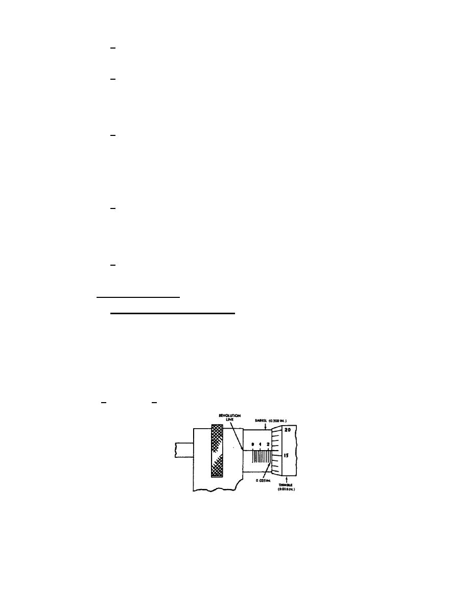
(a) Reading standard micrometer. Reading a micrometer is only a matter
of reading the micrometer scale or counting the revolutions of the thimble and
adding to this any fraction of a revolution. The micrometer screw has 40 threads
per inch. This means that one complete and exact revolution of the micrometer
screw moves the spindle away from or toward the anvil exactly 0.025 inch. The
lines on the barrel (fig 57) conform to the pitch of the micrometer screw, each
line indicating 0.025 inch, and each fourth line being numbered 1, 2, 3, and so
forth. The beveled edge of the thimble is graduated into 25 parts, each line
indicating 0.001 inch, 1/25 of the 0.025 inch covered by one complete and exact
revolution of the thimble. Every fifth line on the thimble is numbered to read a
measurement in thousandths of an inch. Read the measurement shown in figure 57 as
indicated in 1. through 4. below.
Figure 57.
Reading standard micrometer scale.
47


 Previous Page
