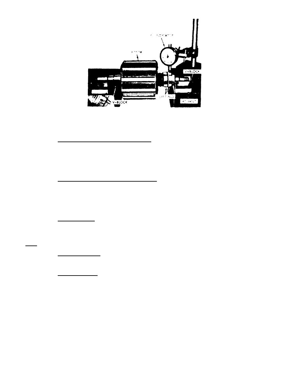
Figure 18.
Testing sliprings for distortion.
19.
TESTING.
After the generator has been assembled, you must test it for
proper performance.
a. Test setup with regulator removed. To check generator output without
terminals 1 and 5 and 2 and 3 of the connector as shown in A, Foldout 2. Install
the drive end housing on the generator. Connect the generator as shown in B,
Foldout 2. Operate the generator at the speeds indicated in C, Foldout 2. Then
adjust the variable resistor until the generator is producing the indicated voltage
at the rated amperage.
b. Test setup with regulator installed. Install the regulator in the
generator as directed. Connect the generator as shown in D, Foldout 2. The 0-to
generator output voltage.
Note. -The ignition switch must be closed at all times during tests.
This switch
completes the field coil circuit.
c. Heat run test. Operate the generator under the conditions given in C,
Foldout 2. Adjust the generator output voltage to 28 volts by removing the pipe
plug (A, 24, Foldout 1) and rotating the potentiometer adjusting screw. Operate
for 1 hour. Check that temperature rise does not exceed 280 F.
Note. - Perform this test at room temperature of 80 F.
d. Speed load test. Immediately after the heat. run test, operate the
generator at the speeds indicated in table C, Foldout 2. Generator output must be
at or above the indicated output.
e. Overspeed test. Disconnect the generator from the electrical circuit.
Then operate the generator at the speed and for the time interval specified in
table C, Foldout 2. Listen for any unusual noise that might indicate mechanical
failure.
OS 010, 2-P16


 Previous Page
