• Home
  • Download PDF
  • Order CD-ROM
  • Order in Print

Home > Ordnance Documents and other related manuals > > Figure 23. Main Engine Upper Covers ( Cont)
Figure 22. Main Engine Upper Covers
Figure 24. Fuel Return and Supply Lines And Cooling Fan Drive.

Maintenance of the M88A1
Page Navigation
  43    44    45    46    47  48  49    50    51    52    53  

MAINTENANCE OF THE M88A1 - OD1672
- LESSON 2/TASK 1
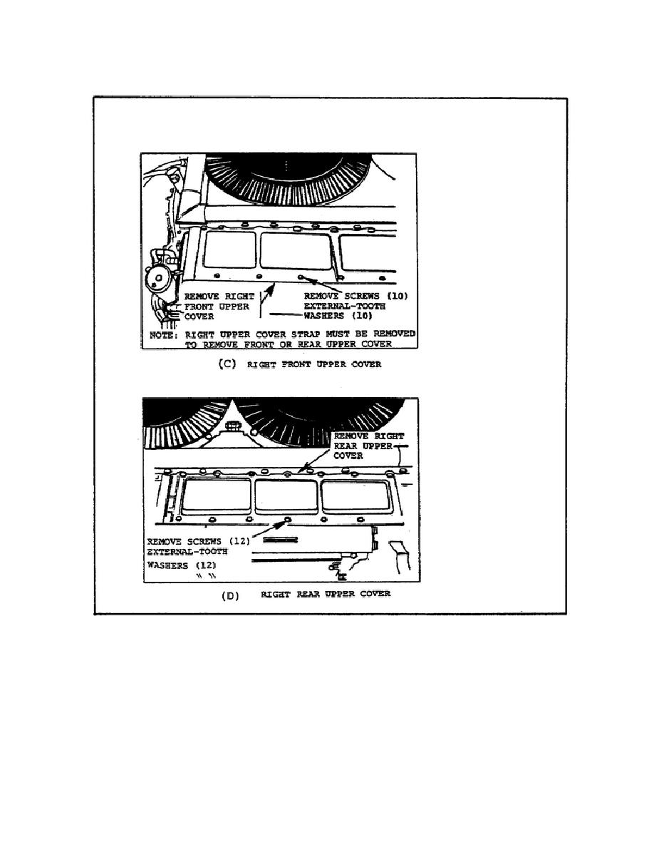
FIGURE 23. MAIN ENGINE UPPER COVERS
(CONTINUED).
Step 4.  Install a sleeve spacer on each fan drive vertical shaft (figure
24, view C, on the following page) and secure each fan drive with the
cooling fan nut.
Step 5.
Start the engine and check for fuel leakage at all fuel supply
lines to fuel injector nozzles and to fuel pump outlet ports, and fuel
return lines to injector nozzle connections.
49


Western Governors University

< Previous Page
Index ^
Next Page >

Privacy Statement
Press Release
Contact

© Copyright Integrated Publishing, Inc.. All Rights Reserved. Design by Strategico.